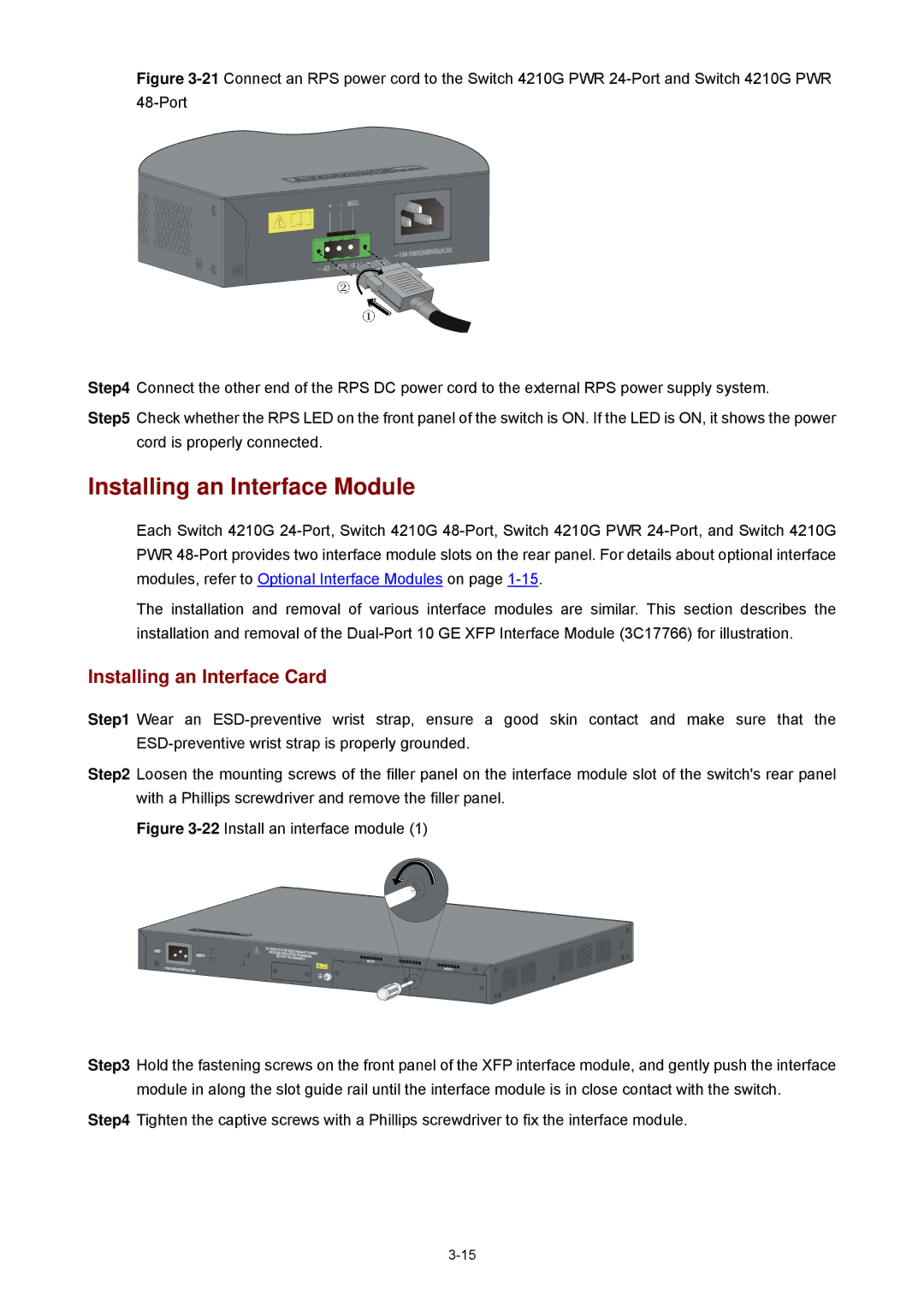
Figure 3-21Connect an RPS power cord to the Switch 4210G PWR 24-Port and Switch 4210G PWR 48-Port

Step4 Connect the other end of the RPS DC power cord to the external RPS power supply system.

Step5 Check whether the RPS LED on the front panel of the switch is ON. If the LED is ON, it shows the power cord is properly connected.

Installing an Interface Module

Each Switch 4210G 24-Port, Switch 4210G 48-Port, Switch 4210G PWR 24-Port, and Switch 4210G PWR 48-Port provides two interface module slots on the rear panel. For details about optional interface modules, refer to Optional Interface Modules on page 1-15.

The installation and removal of various interface modules are similar. This section describes the installation and removal of the Dual-Port 10 GE XFP Interface Module (3C17766) for illustration.

Installing an Interface Card

Step1 Wear an ESD-preventive wrist strap, ensure a good skin contact and make sure that the ESD-preventive wrist strap is properly grounded.

Step2 Loosen the mounting screws of the filler panel on the interface module slot of the switch's rear panel with a Phillips screwdriver and remove the filler panel.

Figure 3-22Install an interface module (1)

Step3 Hold the fastening screws on the front panel of the XFP interface module, and gently push the interface module in along the slot guide rail until the interface module is in close contact with the switch.

Step4 Tighten the captive screws with a Phillips screwdriver to fix the interface module.

3-15

Page 44
Image 44
3Com 4210G manual Installing an Interface Module, Installing an Interface Card