Connecting the Grounding Cable
z
z
Correctly connecting the chassis grounding cable is crucial to the lightning protection and electromagnetic susceptibility (EMS) of a switch.
The power and grounding terminals in this section are for illustration only.
The power input end of the switch is connected with a noise filter, whose central ground is directly connected to the chassis, forming the
When a Grounding Strip is Available
When a grounding strip is available at the installation site, attach one end of the
Step1 Remove the grounding screw from the rear panel of the switch chassis.
Step2 Put the supplied OT terminal of the PGND cable on the grounding screw.
Step3 Fasten the grounding screw, which is attached with the OT terminal of the PGND cable, into the grounding screw hole with a screwdriver.
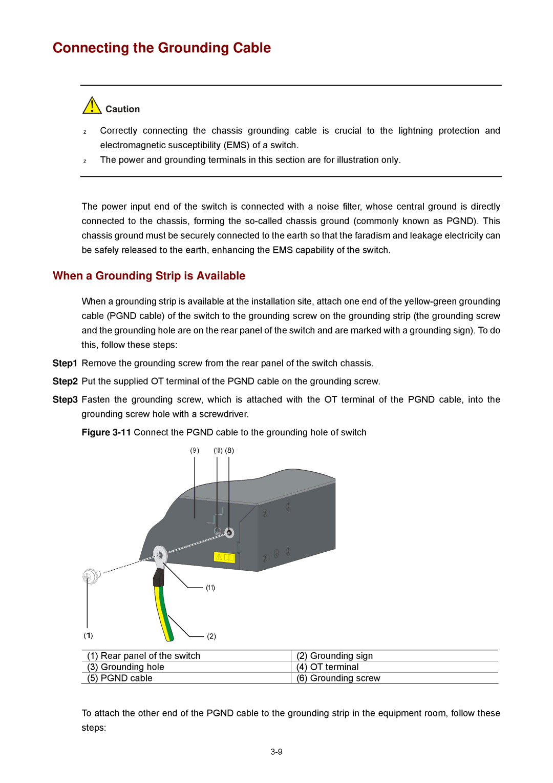
Figure 3-11 Connect the PGND cable to the grounding hole of switch
(1) Rear panel of the switch | (2) | Grounding sign | |
(3) | Grounding hole | (4) | OT terminal |
(5) | PGND cable | (6) | Grounding screw |