3Com Router 5682 (3C13759) 23
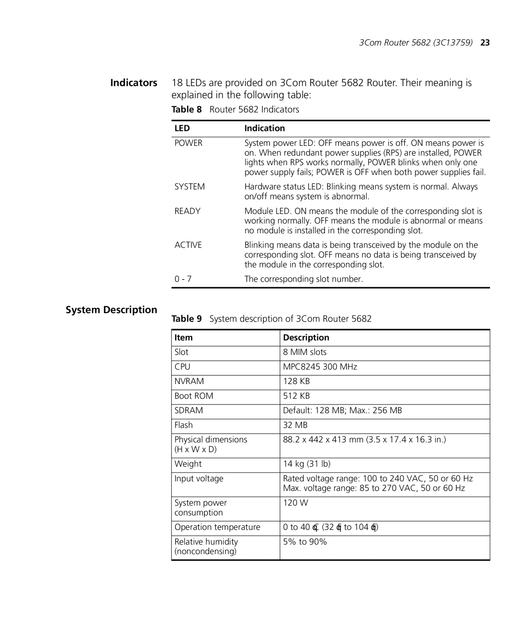
Indicators 18 LEDs are provided on 3Com Router 5682 Router. Their meaning is explained in the following table:
Table 8 Router 5682 Indicators
LED | Indication |
|
|
POWER | System power LED: OFF means power is off. ON means power is |
| on. When redundant power supplies (RPS) are installed, POWER |
| lights when RPS works normally, POWER blinks when only one |
| power supply fails; POWER is OFF when both power supplies fail. |
SYSTEM | Hardware status LED: Blinking means system is normal. Always |
| on/off means system is abnormal. |
READY | Module LED. ON means the module of the corresponding slot is |
| working normally. OFF means the module is abnormal or means |
| no module is installed in the corresponding slot. |
ACTIVE | Blinking means data is being transceived by the module on the |
| corresponding slot. OFF means no data is being transceived by |
| the module in the corresponding slot. |
0 - 7 | The corresponding slot number. |
|
|
System Description
Table 9 System description of 3Com Router 5682
Item | Description |
|
|
Slot | 8 MIM slots |
|
|
CPU | MPC8245 300 MHz |
|
|
NVRAM | 128 KB |
|
|
Boot ROM | 512 KB |
|
|
SDRAM | Default: 128 MB; Max.: 256 MB |
|
|
Flash | 32 MB |
|
|
Physical dimensions | 88.2 x 442 x 413 mm (3.5 x 17.4 x 16.3 in.) |
(H x W x D) |
|
|
|
Weight | 14 kg (31 lb) |
|
|
Input voltage | Rated voltage range: 100 to 240 VAC, 50 or 60 Hz |
| Max. voltage range: 85 to 270 VAC, 50 or 60 Hz |
|
|
System power | 120 W |
consumption |
|
|
|
Operation temperature | 0 to 40°C (32°F to 104°F) |
|
|
Relative humidity | 5% to 90% |
(noncondensing) |
|
|
|
