CCB - Ten Position Dipswitch (Central Control Section) SW1:
Dipswitch configurations are READ ONLY ON POWER UP. These switches are only to be set at the factory or by authorized trained personnel! Once set the boiler will operate according to the chosen options. If a switch is changed, power must be cycled before the change will take effect. The status of all dipswitches can be observed on the system status screen on the UIM.
CCB/FCB Dipswitches:
Dipswitches Function |
|
| Switch Position |
|
| ||
Boilers | Water Heaters | ||||||
| |||||||
Switch 1: Selection of the type of boiler application: | On | = | GB/LB | Off | = | GW/LW | |
Switch 2: Trials for ignition: | On | = | 3 | Off | = | 1 | |
Switch 3: IRI Gas Valve Option: | On = IRI | Off | = No IRI | ||||
Switch 4: Controlling Probe: | On | = | Tank (Remote) | Off = Inlet | |||
Switch 5: Powered Venter: | On = Yes | Off = | No | ||||
Switch 6: Low Water Cut Off: (LWCO) | On = Yes | Off = | No | ||||
Switch 7: Low Gas Pressure | On = Yes | Off = | No | ||||
Switch 8: Spare: |
|
|
|
|
|
| |
Switch 9 & 10. Number stages (FCB's): | 9 |
| 10 | #stages | |||
| Off |
| Off | = 1 |
|
| |
| Off |
| On | = 2 |
|
| |
| On |
| Off | = 3 |
|
| |
| On |
| On | = 4 |
|
| |
|
|
|
|
|
|
| |
NOTE: If the unit powers up with the number of stages selected by dip switches exceeding the number of FCBs, the CCB will detect this condition and go into a hard lockout. After changing the dipswitches to the correct number of stages, the power must be cycled on and off to accept the change.
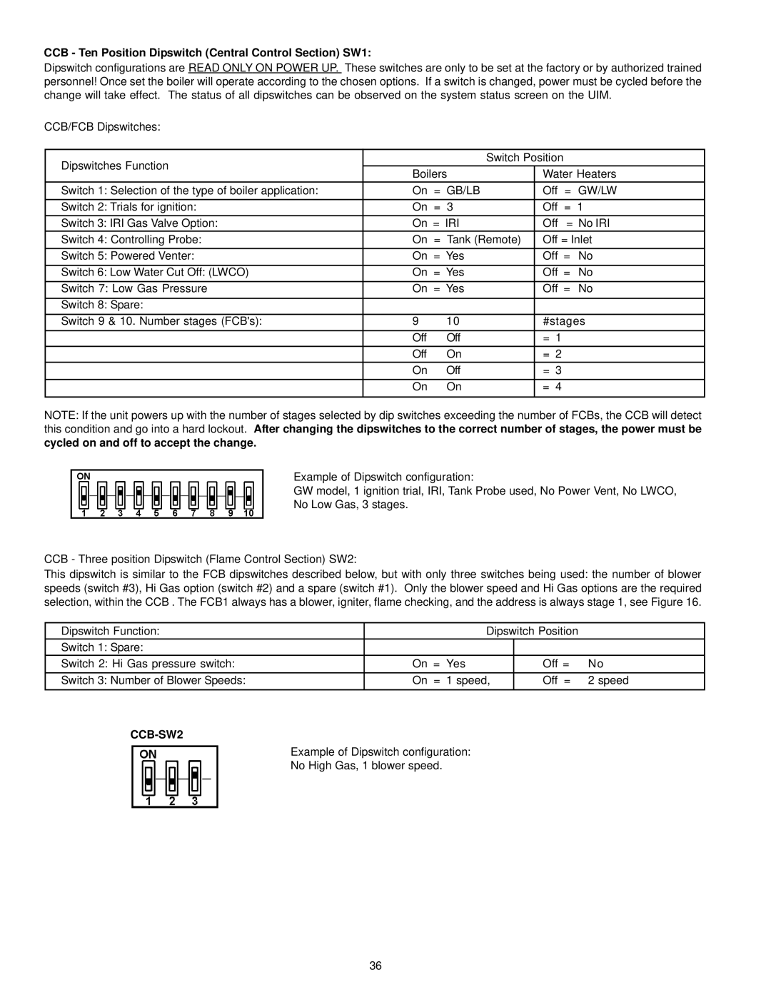
Example of Dipswitch configuration:
GW model, 1 ignition trial, IRI, Tank Probe used, No Power Vent, No LWCO,
No Low Gas, 3 stages.
CCB - Three position Dipswitch (Flame Control Section) SW2:
This dipswitch is similar to the FCB dipswitches described below, but with only three switches being used: the number of blower speeds (switch #3), Hi Gas option (switch #2) and a spare (switch #1). Only the blower speed and Hi Gas options are the required selection, within the CCB . The FCB1 always has a blower, igniter, flame checking, and the address is always stage 1, see Figure 16.
Dipswitch Function: | Dipswitch Position |
| |
Switch 1: Spare: |
|
|
|
Switch 2: Hi Gas pressure switch: | On = Yes | Off = | No |
Switch 3: Number of Blower Speeds: | On = 1 speed, | Off = | 2 speed |
CCB-SW2
Example of Dipswitch configuration:
No High Gas, 1 blower speed.
36