“Tank Probe” | Tank (Remote) probe shorted or open | Flashing | HARD |
| Caused when the thermistor in the probe or the wiring is shorted or disconnected. Check the probe. Note: | ||
| the thermistor and wiring can be checked by disconnecting the probe from the CCB and reading the | ||
| resistance across the two active pins on the connector at the end of the probe cable. The value should be | ||
| approximately 10K ohms (value will change slightly with changes in temperature). |
| |
“Igniter Stg*” | Igniter current is too low | Flashing | HARD |
| Caused by a low current draw problem with the igniter. This may occur if the igniter is old, damaged, or | ||
| disconnected and no longer draws the proper level of current. This condition will affect the ability of the | ||
| igniter to get hot enough to fire the gas properly. Check the igniter and its associated wiring. |
| |
“Igniter Pwr Stg*” | Improper power applied to the igniter circuit | Flashing | HARD |
| Caused by improper line power being applied to the igniter circuitry. Check line connections. | ||
Paying particular attention to the earth ground connection. Also check that line voltage does not exceed 132 |
| ||
vac rms. |
|
|
|
“Igniter Hdwr Stg*” | Hardware problems with igniter circuit | Flashing | HARD |
PREVENTATIVE MAINTENANCE
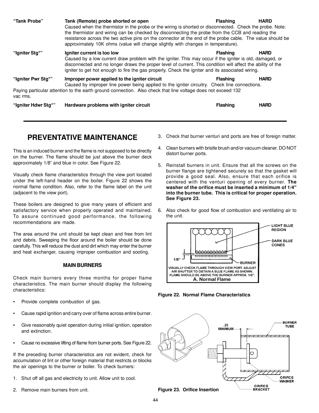
This is an induced burner and the flame is not supposed to be directly on the burner. The flame should be just above the burner deck approximately 1/8” and blue in color. See Figure 22.
Visually check flame characteristics through the view port located under the
These boilers are designed to give many years of efficient and satisfactory service when properly operated and maintained. To assure continued good performance, the following recommendations are made.
The area around the unit should be kept clean and free from lint and debris. Sweeping the floor around the boiler should be done carefully. This will reduce the dust and dirt which may enter the burner and heat exchanger, causing improper combustion and sooting.
MAIN BURNERS
Check main burners every three months for proper flame characteristics. The main burner should display the following characteristics:
•Provide complete combustion of gas.
•Cause rapid ignition and carry over of flame across entire burner.
•Give reasonably quiet operation during initial ignition, operation and extinction.
•Cause no excessive lifting of flame from burner ports. See Figure 22.
If the preceding burner characteristics are not evident, check for accumulation of lint or other foreign material that restricts or blocks the air openings to the burner or boiler. To check burners:
1.Shut off all gas and electricity to unit. Allow unit to cool.
2.Remove main burners from unit.
3.Check that burner venturi and ports are free of foreign matter.
4.Clean burners with bristle brush and/or vacuum cleaner. DO NOT distort burner ports.
5.Reinstall burners in unit. Ensure that all the screws on the burner flange are tightened securely so that the gasket will provide a good seal. Also, ensure that each orifice is centered with the venturi opening of every burner. The washer of the orifice must be inserted a minimum of 1/4" into the burner tube. This is critical for proper operation. See Figure 23.
6.Also check for good flow of combustion and ventilating air to the unit.
Figure 22. Normal Flame Characteristics
Figure 23. Orifice Insertion
44