FCB: Eight-Position Dipswitch
The first three switches are similar to the switch setup of SW2 on the CCB. The remaining five switches are required for the function of igniter, blower, flame detection, and to address the firing stage. NOTE: When switch 5 is set to OFF (no blower), switch 3 (blower speed) is ignored.
Dipswitch Function: |
|
| Dipswitch Position |
| |
Switch 1: Spare: |
|
|
|
|
|
Switch 2: Hi Gas pressure switch: | On = | Yes |
| Off = | No |
Switch 3: Number of Blower Speeds: | On = | 1 speed, | Off = | 2 speed | |
Switch 4: Igniter used: | On = | Yes, |
| Off = | No |
Switch 5: Blower used: | On = Yes, |
| Off = | No | |
Switch 6: Flame Checked: | On = | Yes, |
| Off = | No |
Switch 7 & 8. Stage selection: | 7 | 8 |
| Stage # |
|
| Off | Off |
| Not allowed | |
| On | Off |
| 2 |
|
| Off | On |
| 3 |
|
| On | On |
| 4 |
|
*When switch 5 is in off (no blower) position, switch 3 (blower speeds) is ignored.
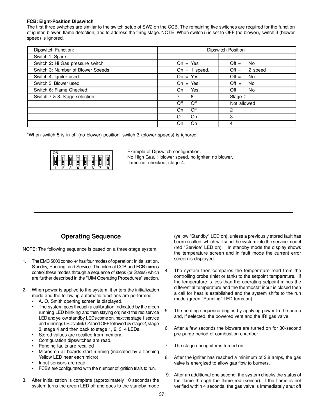
Example of Dipswitch configuration:
No High Gas, 1 blower speed, no igniter, no blower, flame not checked, stage 4.
Operating Sequence
NOTE: The following sequence is based on a
1.The EMC 5000 controller has four modes of operation: Initialization, Standby, Running, and Service. The internal CCB and FCB micros control these modes through a sequence of steps (or States) which are further described in the "UIM Operating Procedures" section.
2.When power is applied to the system, it enters the initialization mode and the following automatic functions are performed:
•A. O. Smith opening screen is displayed.
•The system goes through a calibration indicated by the green running LED blinking and then staying on; next the red service LED and yellow standby LEDs come on, next the stage 1 service and runnings LEDs blink ON and OFF followed by stage 2, stage 3, stage 4 and then back to stage 1, 2, 3, 4 LEDs.
•Stored values are recalled from memory.
•Configuration dipswitches are read.
•Pending faults are recalled
•Micros on all boards start running (indicated by a flashing Yellow LED near each micro)
•Input sensors are read
•FCB's are configurated with the number of ignition trials to run.
3.After initialization is complete (approximately 10 seconds) the system turns the green LED off and goes to the standby mode
(yellow "Standby" LED on), unless a previously stored fault has been recalled, which will send the system into the service model (red "Service" LED on). In standby mode the display shows the temperature screen and in fault mode the current error screen is displayed.
4.The system then compares the temperature read from the controlling probe (inlet or tank) to the setpoint temperature. If the temperature is less than the operating setpoint minus the differential temperature and the thermostat input is closed then a call for heat is established and the system shifts to the run mode (green "Running" LED turns on).
5.The heating sequence begins by applying power to the pump and, if selected, the powered vent and the IRI gas valve.
6.After a few seconds the blowers are turned on for
7.The stage one igniter is turned on.
8.After the igniter has reached a minimum of 2.8 amps, the gas valve is energized to allow gas flow to burners.
9.After an additional one second, the system checks the status of the flame through the flame rod (sensor). If the flame is not verified within 4 seconds, the gas valve is immediately shut off
37