Removing the LCD Bezel
1.See “Removing the Touchpad Board” on page 67.
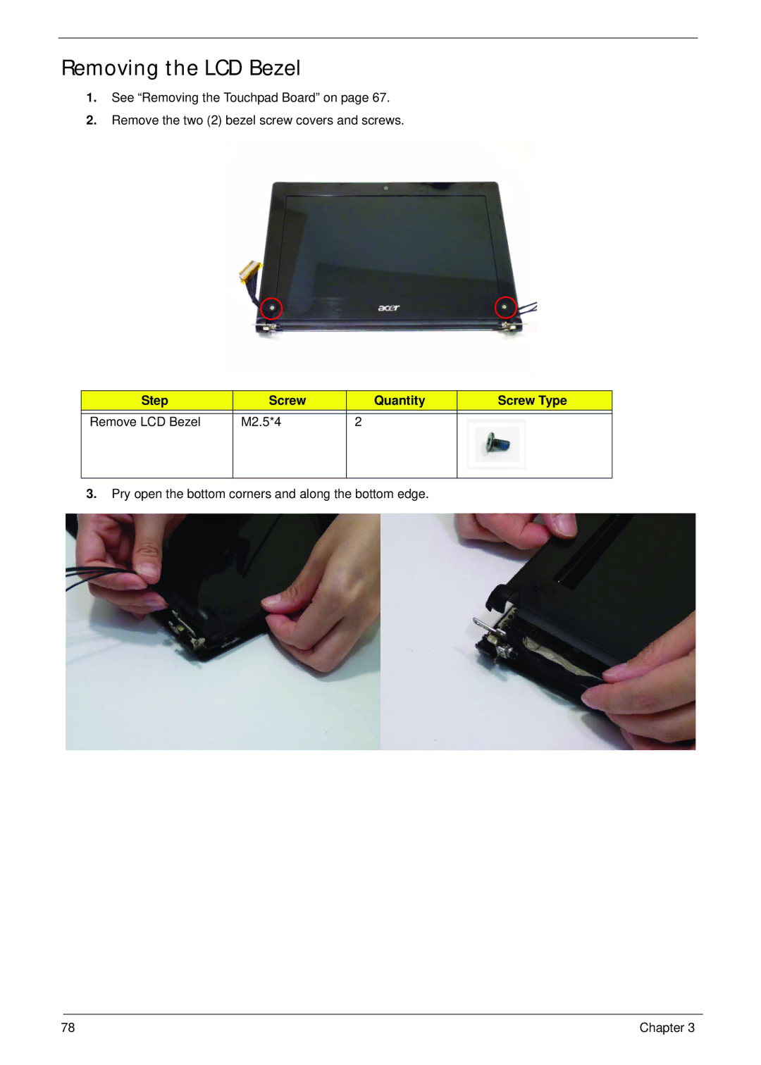
2.Remove the two (2) bezel screw covers and screws.
Step | Screw | Quantity | Screw Type |
|
|
|
|
Remove LCD Bezel | M2.5*4 | 2 |
|
|
|
|
|
3.Pry open the bottom corners and along the bottom edge.
78 | Chapter 3 |
1.See “Removing the Touchpad Board” on page 67.
2.Remove the two (2) bezel screw covers and screws.
Step | Screw | Quantity | Screw Type |
|
|
|
|
Remove LCD Bezel | M2.5*4 | 2 |
|
|
|
|
|
3.Pry open the bottom corners and along the bottom edge.
78 | Chapter 3 |