Main Unit Disassembly Process
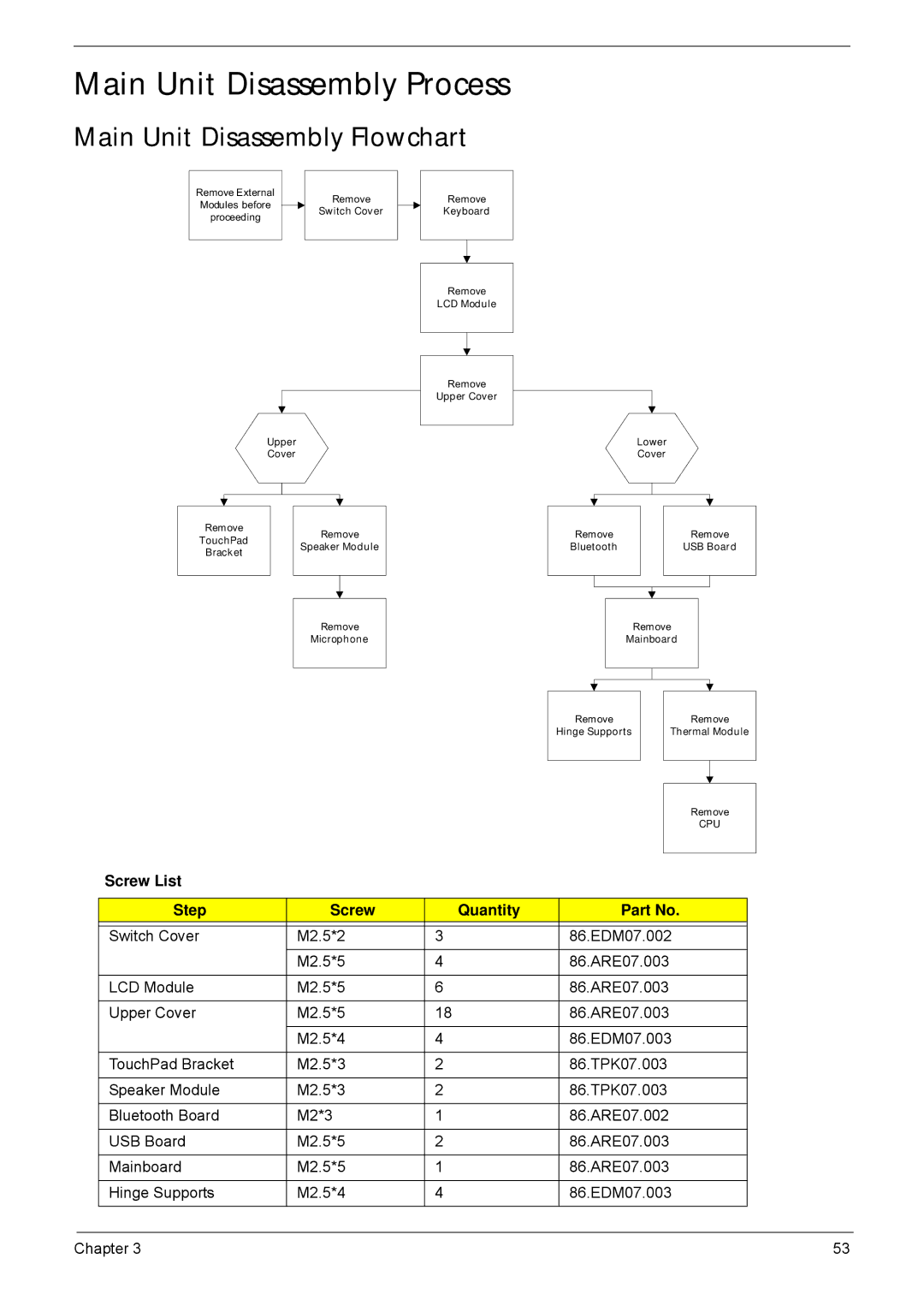
Main Unit Disassembly Flowchart
Remove External |
|
| Remove |
|
Modules before |
|
|
| |
|
| Switch Cover |
| |
proceeding |
|
|
| |
|
|
|
| |
|
|
|
|
|
Upper
Cover
Remove
Keyboard
Remove
LCD Module
Remove
Upper Cover
Lower Cover
Remove |
| Remove | |
TouchPad |
| ||
| Speaker Module | ||
Bracket |
| ||
|
|
| |
|
|
|
|
|
|
|
|
|
|
|
|
|
| Remove | |
|
| Microphone | |
|
|
|
|
Remove |
|
|
| Remove | ||
Bluetooth |
|
|
| USB Board | ||
|
|
|
|
|
|
|
|
|
|
|
|
|
|
Remove
Mainboard
Remove |
| Remove | |
Hinge Supports |
| Thermal Module | |
|
|
|
|
|
|
|
|
Remove
CPU
Screw List
Step | Screw | Quantity | Part No. |
|
|
|
|
Switch Cover | M2.5*2 | 3 | 86.EDM07.002 |
| M2.5*5 | 4 | 86.ARE07.003 |
|
|
|
|
LCD Module | M2.5*5 | 6 | 86.ARE07.003 |
|
|
|
|
Upper Cover | M2.5*5 | 18 | 86.ARE07.003 |
|
|
|
|
| M2.5*4 | 4 | 86.EDM07.003 |
|
|
|
|
TouchPad Bracket | M2.5*3 | 2 | 86.TPK07.003 |
|
|
|
|
Speaker Module | M2.5*3 | 2 | 86.TPK07.003 |
|
|
|
|
Bluetooth Board | M2*3 | 1 | 86.ARE07.002 |
|
|
|
|
USB Board | M2.5*5 | 2 | 86.ARE07.003 |
|
|
|
|
Mainboard | M2.5*5 | 1 | 86.ARE07.003 |
|
|
|
|
Hinge Supports | M2.5*4 | 4 | 86.EDM07.003 |
|
|
|
|
Chapter 3 | 53 |