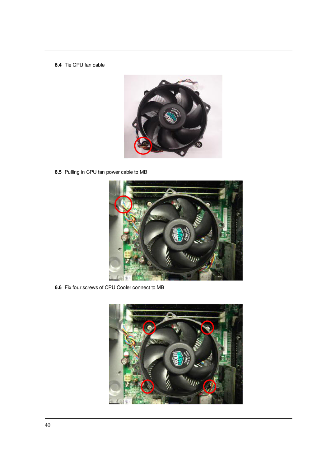
imedia S3811 Service Guide
PRINTED IN TAIWAN
Date
Revision History
Updated
Chapter
Copyright
Disclaimer
SCREEN
Conventions
MESSAGES
Preface
Introducing the Motherboard
Chapter1 Introducing the Motherboard
Introduction
Processor
Features
Operating system
Chipset
Dimensions and weight
BIOS Firmware
Integrated I/O
Label
Mainboard Components
Component
Block Diagram
Icon
imedia S3811
Front view
Component
Icon
Rear view
Lights to indicate the status of wireless
Component
Headphone
Audio Jack Function Table
Color/Use
5.1CH
Component
I/O Port Introduction
first jack is for stereo line-in signal. The second jack is for
Description
Keyboard PS/2 or USB, manufacturing option
System Peripherals
Mouse PS/2 or USB, manufacturing option
Speakers
Card Reader Option
BIOS Hotkey List
Hardware Specifications and Configurations
BIOS
Specification
First-Level Cache Configurations
Specification
Specification
Second-Level Cache Configurations
Specification
Power Management
Specification
IDE Interface
Global Standby Mode
Power Management Function ACPI support function
Device Standby Mode
Suspend Mode
The Standard Configuration
Chapter2 Using BIOS
About the Setup Utility
Entering the Setup Utility
+/-/ :Value F10 :Save & Exit Setup
Setup Utility Menus
CMOS Setup Utility - Copyright C 1985-2010, American Megatrends, Inc
F9 :Load Default Settings
You can download and install updated BIOS for this motherboard from the manufacturer’s Web site. New BIOS provides support for new peripherals, improvements in performance, or fixes for known bugs. Install new BIOS as follows
Product Information
↑↓→← : Move
Hard Disk
Standard CMOS Features
10 54
ATAPI CDROM
Vendor
Device
Hard Disk
ST3320418AS
Quiet Boot Enabled
Advanced BIOS Features
Quick Boot Enabled
↑↓→← : Move
uOptical Disk Drive Priority D/DVD Drives Press Enter
uHard Disk Drive Priority Press Enter
↑↓→← : Move
↑↓→← : Move
u Removable Device Priority Press Enter
1st Drive
u Network Device Priority Press Enter
Boot Up NumLock On
USB Beep Message Disabled
↑↓→← : Move
Intel Turbo BoostEnabled
Advanced Chipset Features
Intel EIST Enabled
Intel XD Bit Enabled
Onboard Graphics Controller
Integrated Peripherals
Disabled
↑↓→← : Move
Power On by RTC Alarm Disabled
Power Management Setup
Deep Power Off Mode Enabled
Power On by PCIE Devices Disabled
Restore On AC Power Loss Last State
Enabled
PC Health Status
↑↓→← : Move
Spread Spectrum Enabled
Frequency/Voltage Control
↑↓→← : Move
Load Default Settings
BIOS Security Features
↑↓→← : Move
If you have made settings that you do not want to save, use the “Exit
Save & Exit Setup
Exit Without Saving
Wire cutter Phillips screwdriver may require different size
Chapter3 Machine Disassembly and Replacement
To disassemble the computer, you need the following tools
General Information
Before You Begin
1. Opening the chassis
Standard Assembly Process
2. Removing PSU bracket
3.1 Remove the screw 3.2 Rotate the bracket
3. Removing HDD bracket
4. Removing front bezel
4.1 Pushing three hooks
4.2 Rotate the front bezel
5. Insert the ODD devices
5.1 Pushing HDD devices into bracket 5.2 Fix two screws
6.1 Motherboard view 6.2 Open the CPU cover
6. Setting the Motherboard
6.3 Put the CPU in the seat and close the cover
6.4 Tie CPU fan cable 6.5 Pulling in CPU fan power cable to MB
6.6 Fix four screws of CPU Cooler connect to MB
DIMM3
DIMM4
DIMM2
DIMM1
7.1 Pushing rear I/O Shield in chassis
7. Assembly motherboard
8. Insert the system Fan
7.2 Insert the motherboard and fix six screws
8.4 Pulling in system fan power cable to MB
8.2 Pushing system fan 8.3 Fix two screw
9. Pulling in Audio/USB1/CR/PANEL cable to MB and put in cable clip
Front
Back
10. Insert the HDD
SATA 2ODD SATA 1HDD
11. Pulling in HDD &ODD SATA cable on Motherboard
SATA 2 SATA
12. Insert VGA card
12.3 Install VGA card on motherboard
12.1 Rotate the bracket 12.2 Remove PCI slot
12.4 Rotate the bracket
13.3 ATV 12V power cable insert
13. Insert the PSU
13.1 Pushing PSU into bracket 13.2 Fix four screws
Insert the ODD power-cable
13.4 ATX power cable insert 13.5 Insert the ODD/HDD power-cable
Long for HDD used Short for ODD used
14. Overview
2.1 Rotate the power-supply
Standard Disassembly Process
2. Removing the power-supply
1. Opening the chassis
2.3 Pulling out the ODD power-cable and HDD power-cable
2.4 Remove four screws
HDD Cable ODD Cable
3. Pulling out the SATA ODD cable and SATA HDD cable
4. Removing the HDD
4.2 Rotate the bracket 4.3 Remove four screws
FrontBack
4.4 Remove the HDD
6. Pulling out the Audio/USB1/CR/PANEL cable
5. Removing the VGA Card
5.1 Rotate the bracket 5.2 Remove the VGA Card
7.1 Pulling out the system Fan cable 7.2 Remove two screws
7. Removing system Fan
7.3 Remove system Fan
8. Removing the Main Board
8.2 Remove the Rear IO Shield 8.3 Remove the RTC battery
8.1 Remove eight screws then you can pull out MB and remove it
8.4 Pulling out the CPU cooler power-cable from the main board
8.5 Remove the four CPU Cooler screws 8.6 Remove the CPU
8.7 Release the four latch show bellow then remove the Memory
9. Removing front bezel
9.1 Pushing three hooks 9.2 Rotate the front bezel
10.1 remove two screws 10.2 Pulling out the ODD
10. Removing the ODD
11. Removing the ODD bracket
11.1 Remove five screws
11.2 Removing the ODD bracket
12.1 Removing top bezel Pushing the hooks 12.2 Removing Cable-Tie
Back
12.3 Pushing the Cable 12.4 Removing power switch & HDD-LED holder
Front
12.5 Pulling out HDD LED cable
12.6 Removing power switch & HDD led cable
12.7 Removing HDD led housing
Power-On Self-Test POST POST Error Messages List Error Symptoms List
Chapter4 Machine Disassembly and Replacement
Undetermined Problems
Power-On Self-Test POST
KB-5
Initializes DMAC-1 & DMAC-2
needed
BIOS Messages
POST Error Messages List
Action/FRU
Action/FRU
BIOS Messages
This message usually indicates that one or more keys have been pressed during the
Action/FRU
Error Symptoms List
Error Symptom
Processor / Processor Fan
Action/FRU
Error Symptom
PCI modem, make sure Wake up by PCI card is set to Enabled
CD/DVD-ROM Drive
Action/FRU
Error Symptom
Power Supply
Video and Monitor
the system. Only pressing power switch
Error Symptom
Other Problems
No system power, or power supply fan is
Undetermined Problems
Installing the Motherboard in a Case
Chapter5 Jumper and Connector Information
Safety Precautions
Choosing a Computer Case
This illustration shows a 3-pin jumper. Pins 1 and 2 are SHORT
Checking Jumper Settings
Setting Jumpers
Do not over-tighten the screws as this can stress the motherboard
Setting Default
Checking Jumper Settings
Jumper Settings
MEENABLE
Connecting 24-pin power cable
Connecting Case Components
24-pin power cable
SYSFAN Cooling Fan Power Connector
CPUFAN Cooling Fan Power Connectors
Signal Name
Signal Name
Power/Sleep/Message waiting LED
Signal Name
Signal Name
Reset Switch
Installing the Processor
Installing Hardware
Before installing the Processor
3. Return Material Authorization RMA requests will be accepted
CPU Installation Procedure
2. DO NOT remove the CPU cap from the socket before installing a CPU
only if the motherboard comes with the cap on the LGA1156 socket
DDR3 SDRAM memory module table
Installing Memory Modules
Installation Procedure
Memory
SATA power cable optional
Installing Serial ATA Hard Drives
SATA cable optional
Installing Add-on Cards
PCIE1X1 Slot
Follow these instructions to install an add-on card
Signal Name
Connecting Optional Devices
Signal Name
GPIO1~2 Button recovery jumper
Signal Name
SATA 1~4 Serial ATA connectors
Signal Name
Signal Name
Description
Chapter6 FRU Field Replaceable Unit List Exploded Diagram
ChassisP5-15L w/ card reader ME BOM
Description
Page
Description
ChassisP5-15L w/o card reader ME BOM
Description
Page
FRU List
The FRU list will be updated later