Manuals
/
Acer
/
Computer Equipment
/
Computer Hardware
Acer
S3811
manual
Insert VGA card
Models:
S3811
1
52
99
99
Download
99 pages
16.71 Kb
49
50
51
52
53
54
55
56
Specs
Install
Error codes
Block Diagram
Pin Signal Name
Connecting Case Components
Dimension
Standard Configuration
Error Symptoms List
Reset Switch
Page 52
Image 52
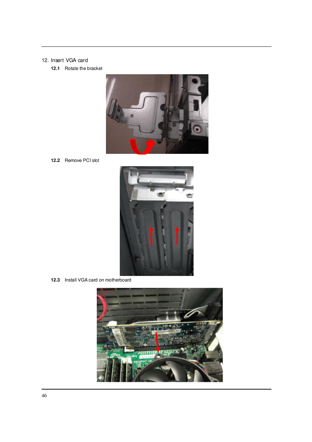
12.
Insert VGA card
12.1
Rotate the bracket
12.2
Remove PCI slot
12.3
Install VGA card on motherboard
46
Page 51
Page 53
Page 52
Image 52
Page 51
Page 53
Contents
Imedia S3811 Service Guide
Date Chapter Updated
Revision History
Copyright
Conventions
Preface
Page
Introducing the Motherboard
Introduction
Features
Dimensions and weight
Bios Firmware
Integrated I/O
Mainboard Components
Label Component
Block Diagram
Imedia S3811
Icon Component Description
Rear view
Color/Use Headphone
Audio Jack Function Table
1CH
Port Introduction
Component Description
System Peripherals
Mouse PS/2 or USB, manufacturing option
Keyboard PS/2 or USB, manufacturing option
Speakers
Card Reader Option
Hardware Specifications and Configurations
Bios Hotkey List
Specification
Main Board Major Chips
System Memory
Cache Memory
Video Interface
Audio Interface
Power Management
IDE Interface
USB Port
Devices Idle Shut Down
Power Management Function Acpi support function
Device Standby Mode
Global Standby Mode
Suspend Mode
Using Bios
About the Setup Utility
Standard Configuration
Entering the Setup Utility
Setup Utility Menus
Updating the Bios
Product Information
Item Help
Standard Cmos Features
Date and Time
A.R.T. Enabled
UAHCI Port1 /Port2
Sata Port0 Auto
Halt On All, But Keyboard
Quick Boot Enabled
Advanced Bios Features
Quiet Boot Enabled
Sequence from Available devices
Removable Device Priority Press Enter
Boot Up NumLock On
USB Beep Message Disabled
Advanced Chipset Features
Integrated Peripherals
Power Management Setup
Restore On AC Power Loss Last State
Smart Fan Enabled
PC Health Status
Spread Spectrum Enabled
Frequency/Voltage Control
Bios Security Features
Load Default Settings
Supervisor Password Not Installed
User Password Not Installed
Save & Exit Setup
Exit Without Saving
Machine Disassembly and Replacement
General Information
Before You Begin
Opening the chassis
Standard Assembly Process
Removing PSU bracket
Removing HDD bracket
Removing front bezel
Insert the ODD devices
Setting the Motherboard
Page
1x1G
2x1G
3x1G
4x1G
Assembly motherboard
Insert the system Fan
Page
Front
Pulling in HDD &ODD Sata cable on Motherboard
Insert VGA card
Insert the PSU
Long for HDD used Short for ODD used
Overview
Standard Disassembly Process
Removing the power-supply
Page
Pulling out the Sata ODD cable and Sata HDD cable
Removing the HDD
FrontBack
Removing the VGA Card
Pulling out the Audio/USB1/CR/PANEL cable
Removing system Fan
Removing the Main Board
Page
Release the four latch show bellow then remove the Memory
Removing the ODD
Removing the ODD bracket
Removing the ODD bracket
Pushing the Cable Removing power switch & HDD-LED holder
Page
Machine Disassembly and Replacement
Power-On Self-Test Post
KB-5
Initializes DMAC-1 & DMAC-2
Needed
Post Error Messages List
Bios Messages Action/FRU
Specifics about the type and location of the memory error
Error Symptoms List
Error Symptom Action/FRU Processor / Processor Fan
Main board and Memory
Hard Disk Drive
Error Symptom Action/FRU CD/DVD-ROM Drive
Audio
Error Symptom Action/FRU Video and Monitor
Power Supply
Parallel/Serial Ports
Keyboard
Error Symptom Action/FRU
Other Problems
Undetermined Problems
Jumper and Connector Information
Safety Precautions
Installing the Motherboard in a Case
Choosing a Computer Case
Checking Jumper Settings
Setting Jumpers
Jumper Settings
Checking Jumper Settings
Jumper Type Description Setting Default IIIustration
Connecting Case Components
Connecting 24-pin power cable
Sysfan Cooling Fan Power Connector Pin Signal Name Function
Atxpoweratx 24-pin Power Connector Pin Signal Name
ATX12V ATX 12V Power Connector Pin Signal Name
Pin Signal Name
Pin Signal Name Function
Power/Sleep/Message waiting LED
Reset Switch
Power Switch
Installing the Processor
Installing Hardware
Before installing the Processor
CPU Installation Procedure
Following illustration shows CPU installation components
Installation Procedure
Installing Memory Modules
Memory Memory Bus
Installing Serial ATA Hard Drives
Sata cable optional Sata power cable optional
Installing Add-on Cards
PCIE1X1 Slot
Onboard PCI interface does not support 64-bit Scsi cards
Connecting Optional Devices
FAUDIO1 Front Panel Audio header
Sata 1~4 Serial ATA connectors
Spdifo Spdif out headerOption
FRU Field Replaceable Unit List Exploded Diagram
ChassisP5-15L w/ card reader ME BOM
Page
ChassisP5-15L w/o card reader ME BOM
Page
FRU List
Top
Page
Image
Contents