Figure1 | Figure2 |
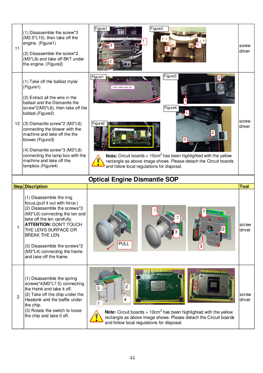
(1)Disassemble the screw*3 (M2.5*L10), then take off the
engine. (Figure1) |
| 1 |
| |
3 | 1 | screw | ||
11 | ||||
| 2 | driver | ||
(2) Disassemble the screw*2 |
|
| ||
|
|
| ||
(M3*L8) and take off BKT under | 2 |
|
| |
the engine. (Figure2) |
|
| ||
|
|
| ||
| Figure1 | Figure3 | 2 |
(1)Take off the ballast mylar (Figure1)
(2)Extract all the wire in the
ballast and the Dismantle the |
| 1 |
| |||||
|
|
|
|
|
|
|
| |
screw*2(M3*L6), then take off the |
|
|
|
|
| Figure4 |
|
|
ballast.(Figure2) |
|
|
|
|
| 1 | screw | |
|
|
|
|
|
| |||
|
|
|
|
|
|
|
| |
12 (3) Dismantle screw*2 (M3*L6) | Figure2 |
| ||||||
|
|
|
|
|
| driver | ||
|
|
|
|
|
|
|
| |
connecting the blower with the |
|
|
|
| 2 | |||
|
|
|
|
| ||||
machine and take off the the |
|
|
|
| ||||
|
|
|
|
|
|
|
| |
blower.(Figure3) |
|
|
| 3 |
| |||
(4) Dismantle screw*3 (M3*L8) |
|
|
|
|
|
|
|
|
|
|
|
|
|
|
|
| |
connecting the lamp box with the |
| Note: Circuit boards > 10cm2 has been highlighted with the yellow |
| |||||
machine and take off the |
| rectangle as above image shows. Please detach the Circuit boards |
| |||||
lampbox.(Figure4) |
| and follow local regulations for disposal. |
| |||||
|
|
|
|
|
|
|
|
|
|
| Optical Engine Dismantle SOP |
|
| ||
Step Discription |
|
|
|
| Tool | |
| (1) Disassemble the ring |
|
|
|
|
|
| focus.(pull it out with force.) |
|
|
|
|
|
| (2) Disassemble the screws*3 |
|
|
| 1 |
|
| (M3*L6) connecting the len and |
|
|
|
| |
|
|
|
|
|
| |
| take off the len carefully. |
|
|
|
|
|
1 | ATTENTION: DON'T TOUCH |
|
|
|
| screw |
THE LEN'S SURFACE OR |
|
|
| 2 | driver | |
| 3 | |||||
| BREAK THE LEN. |
|
| |||
|
|
|
|
|
| |
|
|
|
|
|
|
|
| (3) Disassemble the screws*3 |
| PULL |
| 3 |
|
|
|
|
|
| ||
| (M3*L4) connecting the frame |
|
|
|
|
|
| and take off the frame. |
|
|
|
|
|
| (1) Disassemble the spring |
|
|
|
|
|
|
|
| screws*4(M3*L7.5) connecting |
| 2 |
|
|
|
|
|
| the Hsink and take it off. | 3 |
|
|
|
|
| |
|
|
|
|
|
|
| ||
2 | (2) Take off the chip under the |
|
|
|
|
|
| screw |
Heatsink and the baffle under |
| 4 |
|
|
|
| driver | |
| 1 |
|
|
|
| |||
| the chip. |
|
|
|
|
|
| |
|
|
|
|
|
|
|
| |
| (3) Rotate the switch to loose |
|
|
|
|
|
|
|
|
| Note: Circuit boards > 10cm | 2 | has been highlighted with the yellow |
| |||
| the chip and take it off. |
|
|
| ||||
|
| rectangle as above image shows. Please detach the Circuit boards |
| |||||
|
|
|
| |||||
|
|
| and follow local regulations for disposal. |
| ||||
|
|
|
|
|
|
|
|
|
44