Fixed shafts& holes
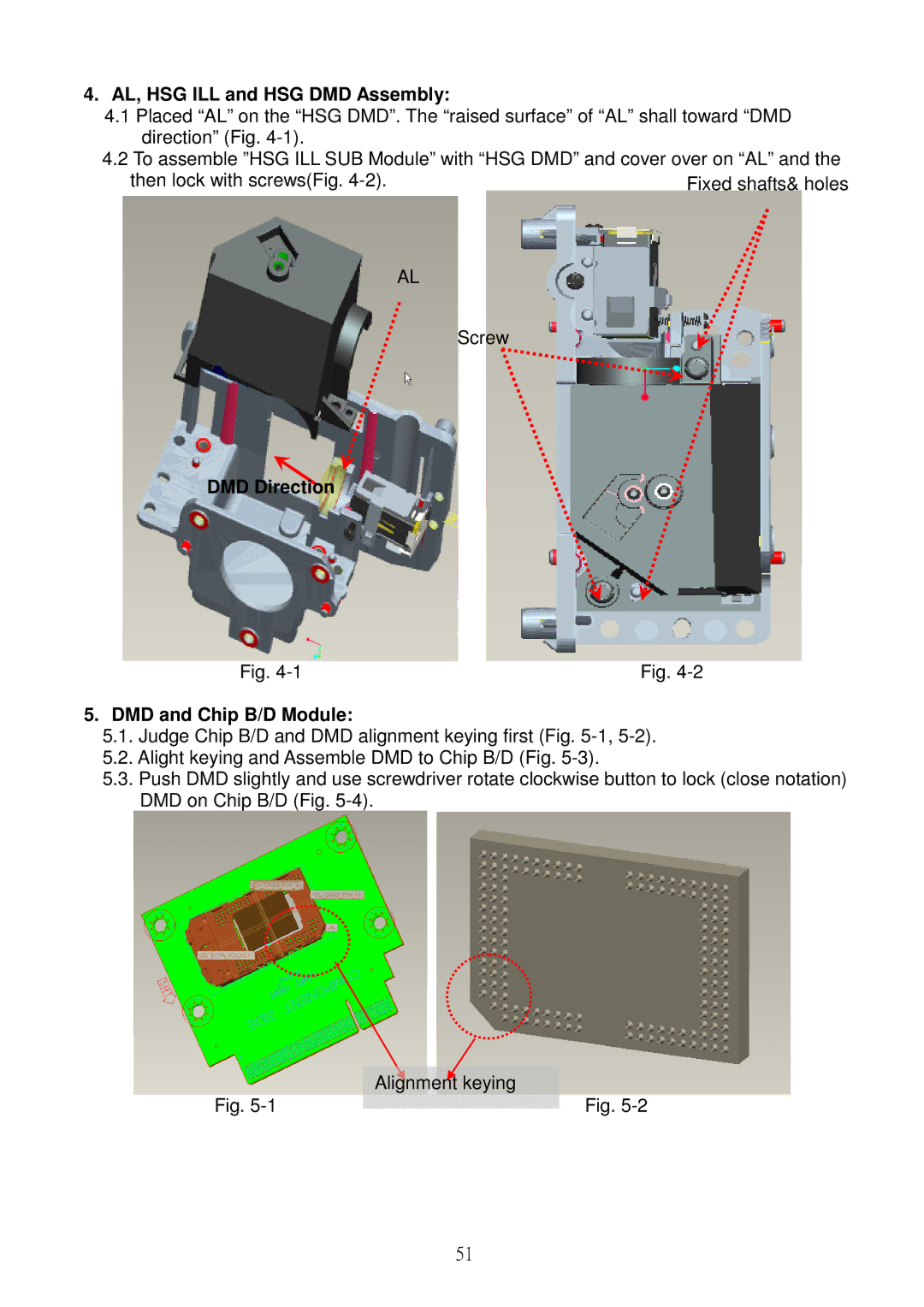
4.AL, HSG ILL and HSG DMD Assembly:
4.1Placed “AL” on the “HSG DMD”. The “raised surface” of “AL” shall toward “DMD direction” (Fig.
4.2To assemble ”HSG ILL SUB Module” with “HSG DMD” and cover over on “AL” and the
then lock with screws(Fig.
AL
Screw
DMD Direction
Fig. | Fig. |
5.DMD and Chip B/D Module:
5.1.Judge Chip B/D and DMD alignment keying first (Fig.
5.2.Alight keying and Assemble DMD to Chip B/D (Fig.
5.3.Push DMD slightly and use screwdriver rotate clockwise button to lock (close notation) DMD on Chip B/D (Fig.
| Alignment keying |
Fig. | Fig. |
51