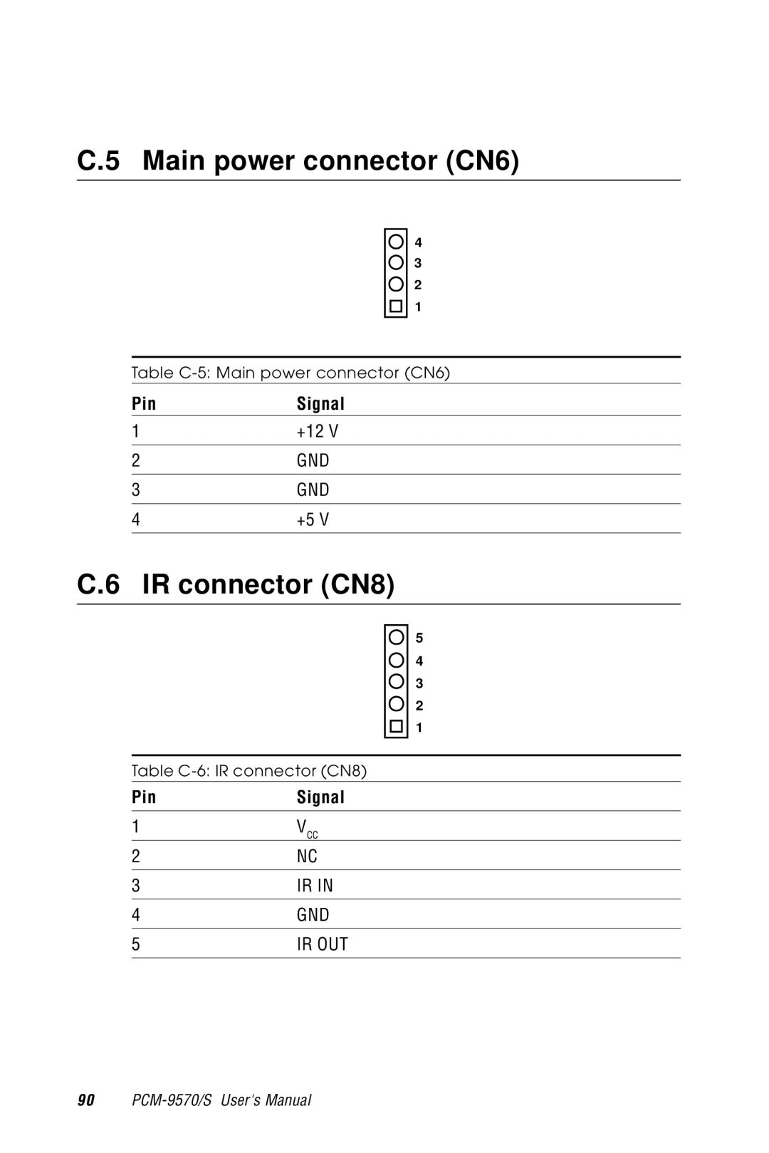
PCM-9570/S
Socket 370 Celeron/Pentium III SBC with LCD, Ethernet and SCSI
Users Manual
Copyright notice
Acknowledgments
1 PCM-9570/S all-in-one single board computer
Packing list
Please refer to Appendix E for the optional interface wiring kit
1 CD disc with utility and drivers 1 Startup Manual
Contents
Chapter 2 Installation
Chapter 1 General Information
2.10
Chapter 3 Software Configuration
Chapter 4 Award BIOS Setup
Chapter 5 PCI SVGA Setup
Appendix B Installing PC/104 Modules
Chapter 6 SCSI Setup and Configurations
Timer
Chapter 7 PCI Bus Ethernet Interface
Appendix F Mechanical Drawings
Appendix D System Assignments
Appendix E Optional Extras
E.1 PCM-10586-4 cable kit for PCM-9570/S
Tables
Table C-19 COM2 port for RS-232, RS-422 and RS-485 CN20
Table C-22 Fan power connector FAN1
Table C-20 CompactFlash card connector CN21
Table C-21 PanelLink connector CN22
Table D-4 IRQ mapping chart
Figures
Figure F-1 PCM-9570/S mechanical drawing - component side
Figure F-2 PCM-9570/S mechanical drawing - solder side
Board layout and dimensions
General Information
Sections include Introduction Features Specifications
This chapter gives background information on the PCM-9570/S
1.1 Introduction
Highly integrated Socket 370 SBC
1.2 Features
1.3 Specifications
Standard SBC functions
PCI SVGA/flat panel interface
Display mode
Solid state disk
PCI bus Ethernet interface
Ultra2 SCSI PCM-9570S only
PanelLink optional
1.4 Board layout and dimensions
Figure 1-1 PCM-9570/S dimensions
6 PCM-9570/S Users Manual
Installation
C H A P T E R
2.1 Jumpers
Label
Function
Label
2.2 Connectors
Please refer to Appendix C for pin assignments
Function
2.3 Locating jumpers
Figure 2-1 Locating jumpers
10 PCM-9570/S Users Manual
Figure 2-2 Locating connectors component side
2.4 Locating connectors
2.4.1 Component side
Chapter 2 Installation
2.4.2 Solder side
Figure 2-3 Locating connectors solder side
12 PCM-9570/S Users Manual
2.5 Setting jumpers
2.6 CPU installation and upgrading
2.6.1 Installing a CPU in the ZIF socket
Enabled
2.6.3 Buzzer enable/disable J9
2.6.2 CMOS clear J1
Disabled
2.7.2 Installing SODIMMs
2.7 Installing DRAM SODIMMs
2.8 IDE hard drive connector CN11
2.7.1 Introduction
2.9 Floppy drive connector CN9
2.8.1 Connecting the hard drive
2.10 Parallel port connector CN12
2.9.1 Connecting the floppy drive
2.12.1 Speaker
2.11 Keyboard and PS/2 mouse connector CN5
2.12 Front panel connector CN18
2.12.2 LED interface
2.13.1 Peripheral power connector, -5 V, -12 V CN14
2.13 Power connectors FAN1, CN14, CN6
2.12.4 Reset switch
2.13.2 Main power connector, +5 V, +12 V CN6
2.14 ATX power control connector CN2, J4
2.14.1 ATX feature connector CN2 and power button J4
2.17 COM-port connector CN20
2.15 ATX power on function select J11
2.16 IR connector CN8
2.17.1 COM2 RS-232/422/485 setting J10
Address range
2.17.2 COM3/COM4 RI pin setting J6
Port
Interrupt
Table 2-9 COM2 RI pin setting J6
RI default setting
Table 2-8 COM1 RI pin setting J6
RI default setting
Table 2-11 COM4 RI pin setting J6
RI default setting
Table 2-10 COM3 RI pin setting J6
Chapter 2 Installation
2.18.3 Ext. flat panel display connector CN17
2.18.1 CRT display connector CN15
2.18.2 Flat panel display connector CN16
2.18 VGA interface connections
2.18.4 Panel type select SW1
Note 2 Pin 6 is reserved for PanelLink setting
Panel type
2.19.2 Network boot
2.19 Ethernet configuration
2.19.1 100Base-T connector CN1
2.19.3 LAN controller power select J12
2.20 Watchdog timer configuration
2.21 USB connectors CN19
2.20.1 Watchdog timer action J2
2.22 SCSI connectors CN4
2.23 PanelLink CN22 optional
30 PCM-9570/S Users Manual
you how to configure the card to
Software Configuration
This chapter details the software configuration information. It shows
Sections include Introduction Ethernet interface configuration
3.1 Introduction
3.2 Ethernet software configuration
For Ethernet installation, please see Chapter
34 PCM-9570/S Users Manual
Award BIOS Setup
This chapter describes how to set BIOS configuration data
C H A P T E R
4.1.1 System configuration verification
4.1 System test and initialization
4.2 Award BIOS setup
4.2.1 Entering setup
4.2.2 Standard CMOS setup
Figure 4-2 CMOS setup screen
4.2.3 BIOS features setup
Figure 4-3 BIOS features setup
Chapter 4 Award BIOS Setup
4.2.4 Chipset features setup
Figure 4-4 Chipset features setup
40 PCM-9570/S Users Manual
4.2.5 Power management setup
Figure 4-5 Power management setup
Chapter 4 Award BIOS Setup
4.2.6 PnP/PCI configuration
Figure 4-6 PnP/PCI configuration
42 PCM-9570/S Users Manual
4.2.7 Integrated peripherals
Chapter 4 Award BIOS Setup
Figure 4-7 Integrated peripherals
4.2.8 Load BIOS defaults
Figure 4-8 Load BIOS defaults
44 PCM-9570/S Users Manual
4.2.9 Change password
Enter Password
Confirm Password
4.2.12 Exit without saving
4.2.11 Save & exit setup
4.2.10 Auto detect hard disk
Figure 4-9 IDE HDD auto detection screen
Windows NT
PCI SVGA Setup
Introduction Installation of SVGA driver for Windows Windows
C H A P T E R
5.1.2 Display memory
5.1 Introduction
5.1.1 Chipset
5.1.3 Display types
5.1.4 Dual/simultaneous display
5.2 Installation of SVGA driver
Enter means pressing the “Enter” key on the
keyboard
Chapter 5 PCI SVGA Setup
5.2.1 Installation for Windows 95/98
a. Select Start , Settings , Control Panel 1. Display , Settings
a. Choose the Adapter label 2. b. Press the Change... button
6. select Trident Cyber 9525 DVD PCI/AGP95mV b. Click the OK button
a. Insert the disc into the CD-ROM drive 5. b. Type D\Biscuit\9570\
c. Press OK
a. Click the Next
a. P re s s Ye s to 9. re b o o t
a. Click Advanced 11. for further adjustment b. Click OK to exit END
Chapter 5 PCI SVGA Setup
The Trident
b. Double click the Display icon a. Choose the Settings label
5.2.2 Installation for Windows NT
a. Select Start, Settings, Control Panel
b. Press the Display Type button a. Press the Change... button
In s e rt th e d is c into th e
d. Click OK to save the setting END
a. Repeat Step 1 in this manual, to select the Settings label
b. Adjust resolution and color 9. c. Click Test to see the result
56 PCM-9570/S Users Manual
5.3 Further information
Chapter 5 PCI SVGA Setup
58 PCM-9570/S Users Manual
SCSI Setup and Configurations
C H A P T E R
segment and is running at SE mode, one or more
6.1 Introduction
If any peripheral is attached to the Ultra2 SCSI
Ultra/Ultra Wide peripherals will be attached to the
6.3 Basic rules for SCSI host adapter and device installation
6.2 Before you begin
Chapter 6 SCSI Setup and Configurations
Copyright 1995, 1998 Symbios Inc PCI-4.12.00
6.4 Configuring the SCSI adapter
Symbios Inc. SDMS TM V 4.0 PCI SCSI BIOS PCI Rev. 2.0
Press Ctrl-C to start Symbios Configuration Utility
6.5 SCSI terminators
either a CD-ROM boot or from the floppy disks, a
6.6 SDMS drivers
When you start the Windows NT installation with
black screen will initially appear with the following
6.7 Utility users guide and installation instructions
For DOS
For Windows 95/98
For NetWare
For Windows NT
For SCO Unix
For OS/2
6.8 Driver and utility installation
68 PCM-9570/S Users Manual
Introduction Installation of Ethernet driver for Windows 95/98/NT
PCI Bus Ethernet Interface
This chapter provides information on Ethernet configuration
Further information
7.1 Introduction
7.2 Installation of Ethernet driver
7.2.1 Installation for MS-DOS and Windows
examples only.You must follow the flow chart
a. Click Add and 2. prepare to install network functions
7.2.2 Installation for Windows 95/98
a. Select Start, Settings 1. Control Panel. b. Double click Network
3. add the Ethernet card
Note 1 The correct file path for Windows 98 is
Biscuit\9570\Lan.100\8139b\Win98
72 PCM-9570/S Users Manual
a. Choose the Adapters label 2. b. Click the Add button a. Press Have
7.2.3 Installation for Windows NT
a. Select Start, Settings 1. Control Panel b. Double click Network
3. Disk
Insert the CD
a. Make sure the configurations of relevant items are set correctly
b. Click OK to reboot E N D
into the D\ drive
7.3 Further information
Chapter 7 PCI Bus Ethernet Interface
76 PCM-9570/S Users Manual
Programming the Watchdog Timer
A P P E N D I
A.1 Programming the watchdog timer
Data
10 REM Watchdog timer example program
80 PCM-9570/S Users Manual
Installing PC/104 Modules
A P P E N D I
B.1 Installing PC/104 modules
82 PCM-9570/S Users Manual
Appendix B Installing PC/104 Modules
Figure B-1 PC/104 module mounting diagram
Figure B-2 PC/104 module dimensions mm ±0.1
P C /1 0 M ounting Support
Number
Signal
Signal
Row A
Pin Assignments
Signal
C.1 Ethernet 10/100Base-T connector CN1
C.2 ATX power feature connector CN2
PinSignal
Function
C.3 SCSI Connector CN4
Table C-3 SCSI connector CN4
Function
Function
Table C-3 SCSI connector CN4 continued
Function
88 PCM-9570/S Users Manual
Table C-4 Keyboard and mouse connector CN5
C.4 Keyboard and PS/2 mouse connector CN5
Signal
Appendix C Pin Assignments
Signal
C.5 Main power connector CN6
C.6 IR connector CN8
Signal
Signal
C.7 Floppy drive connector CN9
Signal
low active
Signal
C.8 IDE hard drive connector CN11
Signal
92 PCM-9570/S Users Manual
Signal
C.9 Parallel port connector CN12
Signal
Table C-9 Parallel port connector CN12
PinSignal
C.10 Backlight connector CN13
C.11 Peripheral power connector CN14
Table C-10 Backlight connector CN13
C.12 CRT display connector CN15
Signal
Signal
Signal
C.13 24-bit LCD display connector CN16
Note 2 The signals shown in parentheses are for 24-bit TFT color bits
Signal
Signal
C.14 Ext. LCD display connector CN17
The model number of the CN16 connector is
Signal
C.15 LCD signal mapping
Table C-15 LCD signal mapping
98 PCM-9570/S Users Manual
Signal
C.16 Front panel connector CN18
C.17 USB connectors CN19
Signal
connector are listed below for your
C.18 COM port connector CN20
with four DSUB-9 male connectors. The
Signal
RS-422
Signal
RS-232
RS-485
Signal
C.19 CompactFlash card connector CN21
Signal
102 PCM-9570/S Users Manual
Signal
C.20 PanelLink connector CN22
Signal
Table C-21 PanelLink connector CN22
Table C-22 Fan power connector FAN1
C.21 Fan power connector FAN1
PinSignal
104 PCM-9570/S Users Manual
System Assignments
A P P E N D I
Addr. range Hex
D.1 System I/O ports
MPU-401 select from 300 ~ 330H 2 bytes
Device
Addr. range Hex
D.2 1st MB memory map
D.3 DMA channel assignments
Device
D.4 IRQ mapping chart
Ethernet interface IRQ select 9, 11, 12 PnP USB IRQ select 9, 11, 12
SCSI IRQ select 9, 11, 12
Optional Extras
A P P E N D I
connector
E.1 PCM-10586-4 cable kit for PCM-9570/S
connector
110 PCM-9570/S Users Manual
E.2 USB cable
E.3 SCSI cables
E.4 24-bit LCD cable adapter
112 PCM-9570/S Users Manual
Mechanical Drawings
A P P E N D I
F.1 Component side
Figure F-1 PCM-9570/S mechanical drawing - component side
114 PCM-9570/S Users Manual
F.2 Solder side
Figure F-2 PCM-9570/S mechanical drawing - solder side
Appendix F Mechanical Drawings
116 PCM-9570/S Users Manual