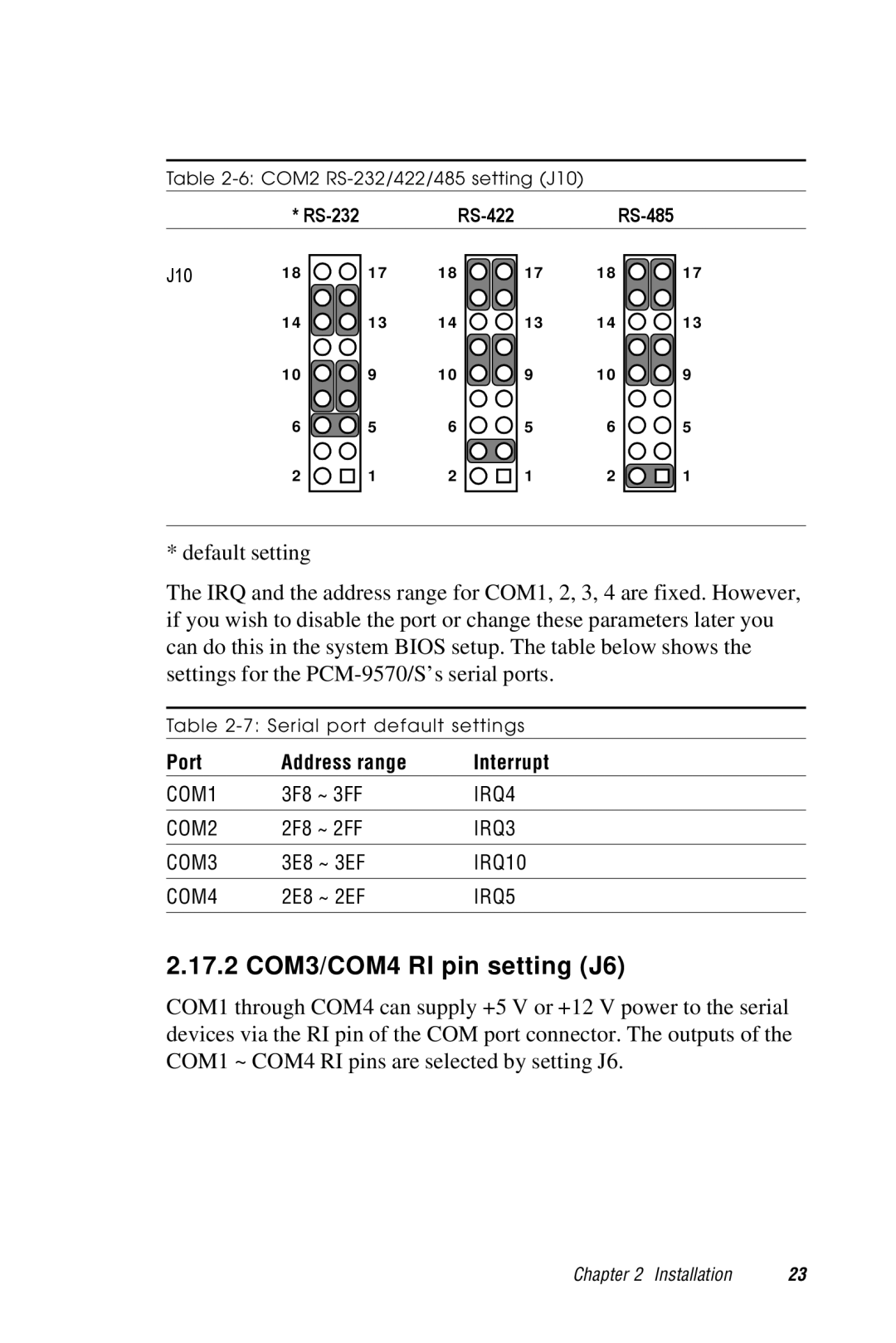
Table
| * |
|
|
| ||
J10 | 18 | 17 | 18 | 17 | 18 | 17 |
| 14 | 13 | 14 | 13 | 14 | 13 |
| 10 | 9 | 10 | 9 | 10 | 9 |
| 6 | 5 | 6 | 5 | 6 | 5 |
| 2 | 1 | 2 | 1 | 2 | 1 |
* default setting
The IRQ and the address range for COM1, 2, 3, 4 are fixed. However, if you wish to disable the port or change these parameters later you can do this in the system BIOS setup. The table below shows the settings for the
Table
Port | Address range | Interrupt |
COM1 | 3F8 ~ 3FF | IRQ4 |
|
|
|
COM2 | 2F8 ~ 2FF | IRQ3 |
|
|
|
COM3 | 3E8 ~ 3EF | IRQ10 |
|
|
|
COM4 | 2E8 ~ 2EF | IRQ5 |
|
|
|
2.17.2 COM3/COM4 RI pin setting (J6)
COM1 through COM4 can supply +5 V or +12 V power to the serial devices via the RI pin of the COM port connector. The outputs of the COM1 ~ COM4 RI pins are selected by setting J6.
Chapter 2 Installation | 23 |