C.14 Ext. LCD display connector (CN17)
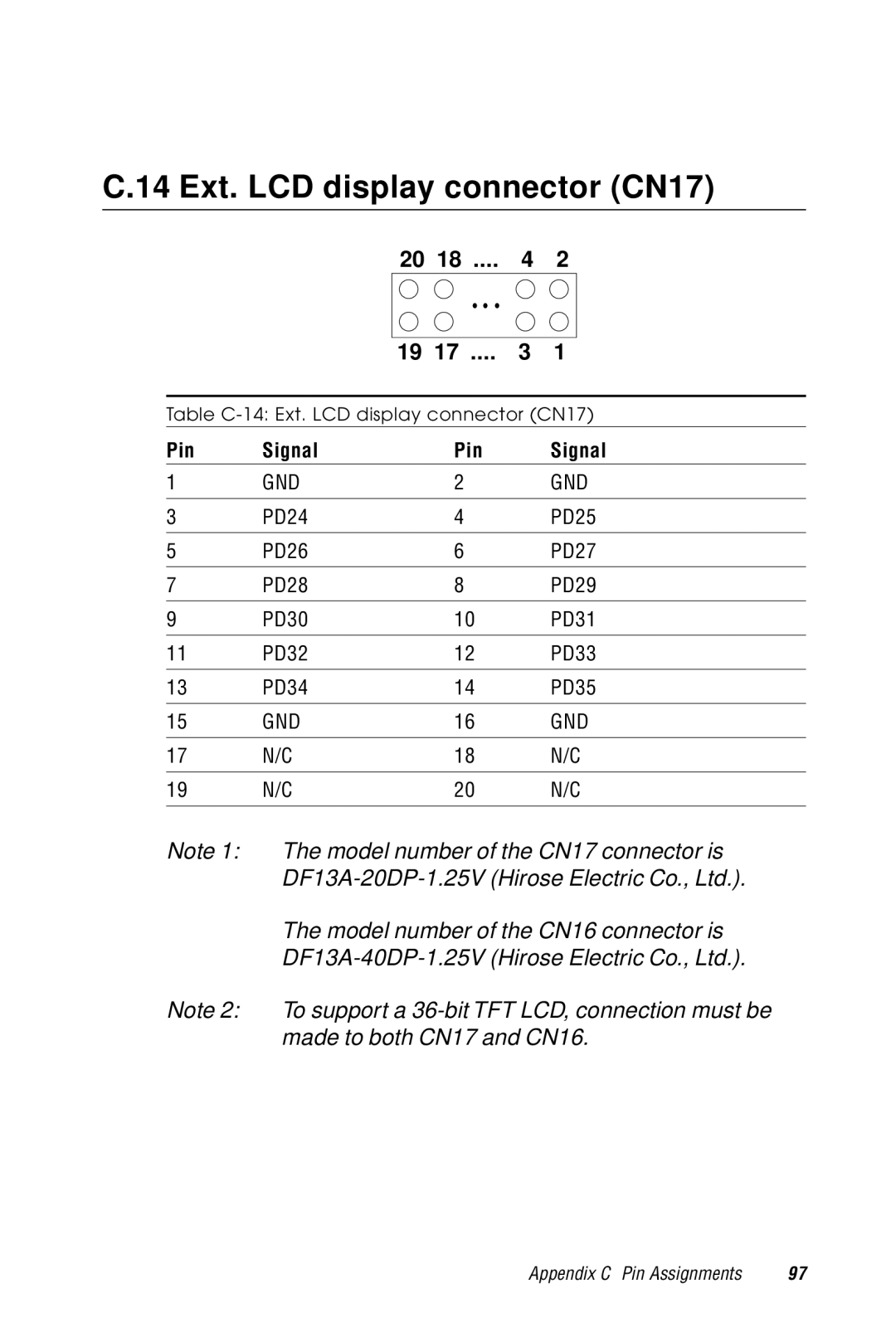
20 | 18 .... | 4 | 2 |
19 | 17 .... | 3 | 1 |
Table
Pin | Signal | Pin | Signal |
1 | GND | 2 | GND |
|
|
|
|
3 | PD24 | 4 | PD25 |
|
|
|
|
5 | PD26 | 6 | PD27 |
|
|
|
|
7 | PD28 | 8 | PD29 |
|
|
|
|
9 | PD30 | 10 | PD31 |
|
|
|
|
11 | PD32 | 12 | PD33 |
|
|
|
|
13 | PD34 | 14 | PD35 |
|
|
|
|
15 | GND | 16 | GND |
|
|
|
|
17 | N/C | 18 | N/C |
|
|
|
|
19 | N/C | 20 | N/C |
|
|
|
|
Note 1: The model number of the CN17 connector is
The model number of the CN16 connector is
Note 2: To support a
Appendix C Pin Assignments | 97 |