1.5.3 Jumper Settings
This section tells how to set the jumpers to configure your card. It gives the card default configuration and your options for each jumper. After you set the jumpers and install the card, you will also need to run the BIOS Setup program (discussed in Chapter 6) to configure the serial port addresses, floppy/hard disk drive types and system operating parameters. Connections, such as hard disk cables, appear in Chapter 2.
For the locations of each jumper, see the board layout diagram depicted earlier in this chapter.
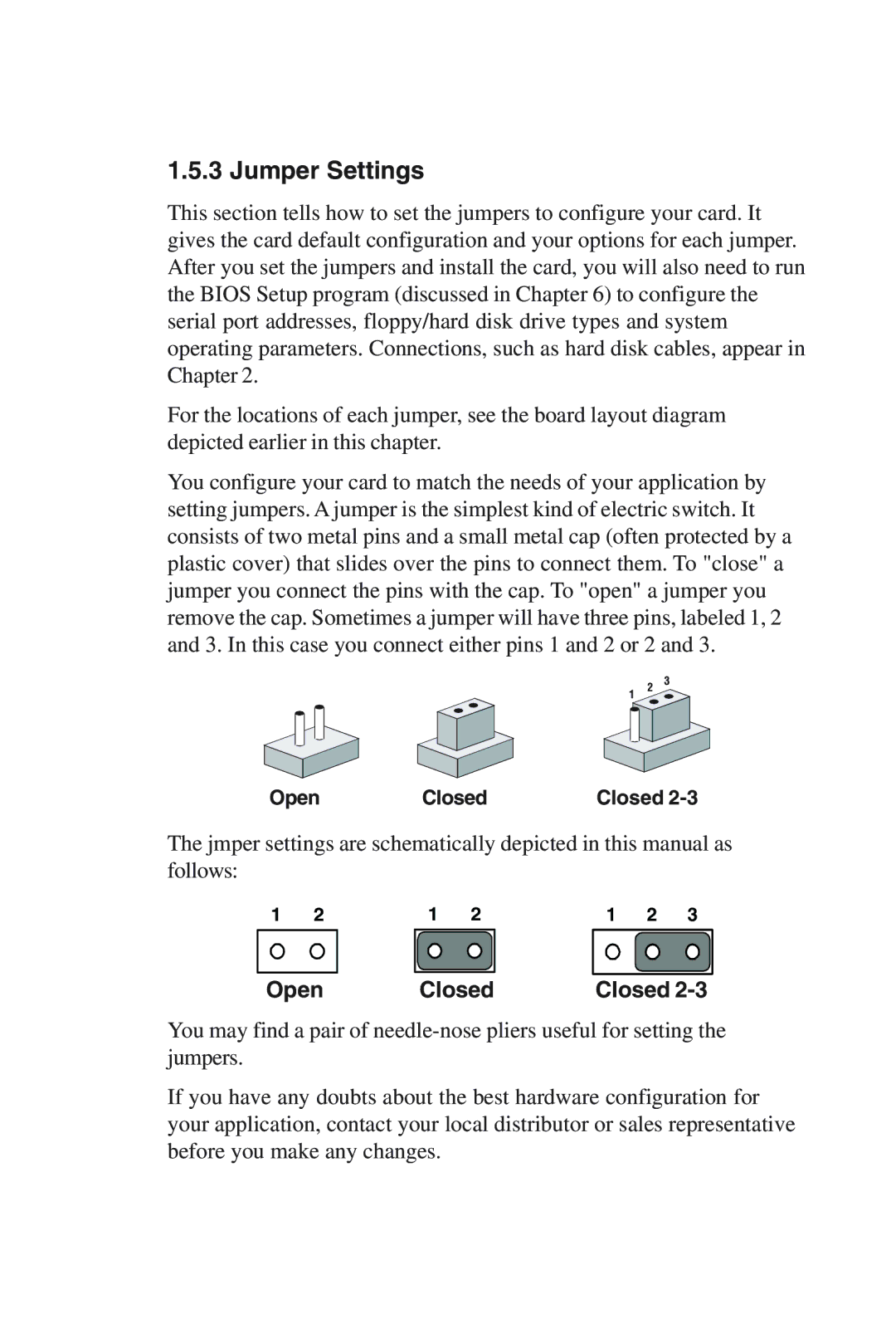
You configure your card to match the needs of your application by setting jumpers. A jumper is the simplest kind of electric switch. It consists of two metal pins and a small metal cap (often protected by a plastic cover) that slides over the pins to connect them. To "close" a jumper you connect the pins with the cap. To "open" a jumper you remove the cap. Sometimes a jumper will have three pins, labeled 1, 2 and 3. In this case you connect either pins 1 and 2 or 2 and 3.
Open Closed
1 | 2 | 3 |
|
|
Closed
The jmper settings are schematically depicted in this manual as follows:
1 21 21 2 3
Open | Closed | Closed |
You may find a pair of
If you have any doubts about the best hardware configuration for your application, contact your local distributor or sales representative before you make any changes.