1.6 Connectors
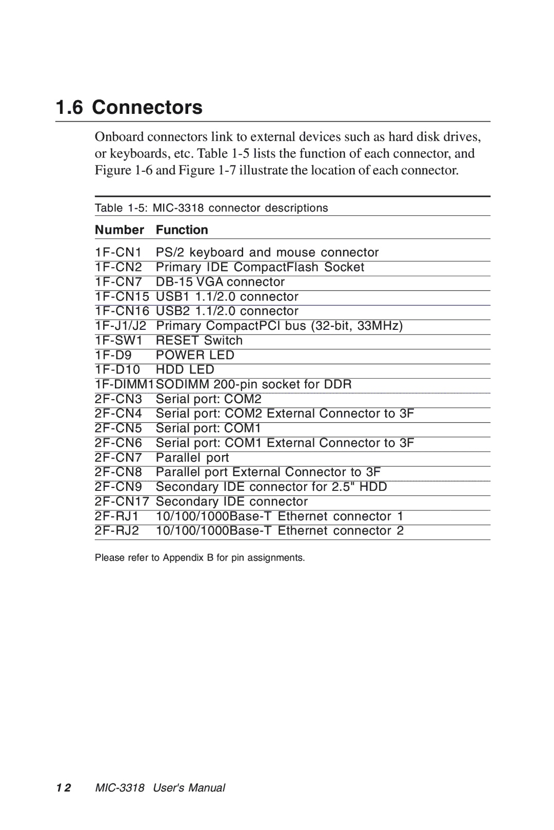
Onboard connectors link to external devices such as hard disk drives, or keyboards, etc. Table
Table
Number | Function |
PS/2 keyboard and mouse connector | |
Primary IDE CompactFlash Socket | |
USB1 1.1/2.0 connector | |
USB2 1.1/2.0 connector | |
Primary CompactPCI bus | |
RESET Switch | |
POWER LED | |
HDD LED | |
Serial port: COM2 | |
Serial port: COM2 External Connector to 3F | |
Serial port: COM1 | |
Serial port: COM1 External Connector to 3F | |
Parallel port | |
Parallel port External Connector to 3F | |
Secondary IDE connector for 2.5" HDD | |
Secondary IDE connector | |
Please refer to Appendix B for pin assignments.
1 2
