Table
Address of |
|
|
|
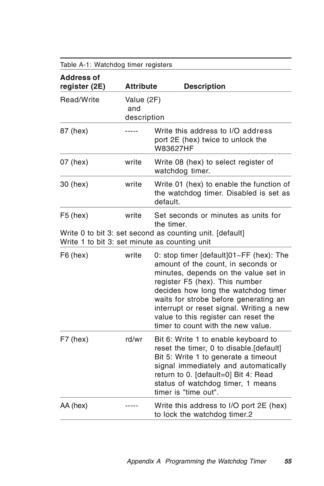
register (2E) | Attribute | Description | |
|
|
| |
Read/Write | Value (2F) |
| |
| and |
|
|
| description |
| |
|
|
| |
87 (hex) | Write this address to I/O address | ||
|
| port 2E (hex) twice to unlock the | |
|
| W83627HF | |
|
|
| |
07 (hex) | write | Write 08 (hex) to select register of | |
|
| watchdog timer. | |
|
|
| |
30 (hex) | write | Write 01 (hex) to enable the function of | |
|
| the watchdog timer. Disabled is set as | |
|
| default. |
|
|
|
| |
F5 (hex) | write | Set seconds or minutes as units for | |
|
| the timer. | |
Write 0 to bit 3: set second as counting unit. [default]
Write 1 to bit 3: set minute as counting unit
F6 (hex) | write | 0: stop timer [default]01~FF (hex): The |
|
| amount of the count, in seconds or |
|
| minutes, depends on the value set in |
|
| register F5 (hex). This number |
|
| decides how long the watchdog timer |
|
| waits for strobe before generating an |
|
| interrupt or reset signal. Writing a new |
|
| value to this register can reset the |
|
| timer to count with the new value. |
|
|
|
F7 (hex) | rd/wr | Bit 6: Write 1 to enable keyboard to |
|
| reset the timer, 0 to disable.[default] |
|
| Bit 5: Write 1 to generate a timeout |
|
| signal immediately and automatically |
|
| return to 0. [default=0] Bit 4: Read |
|
| status of watchdog timer, 1 means |
|
| timer is "time out". |
|
|
|
AA (hex) | Write this address to I/O port 2E (hex) | |
|
| to lock the watchdog timer.2 |
|
|
|
Appendix A Programming the Watchdog Timer | 55 |