Performance Tests
Performance Test Procedures
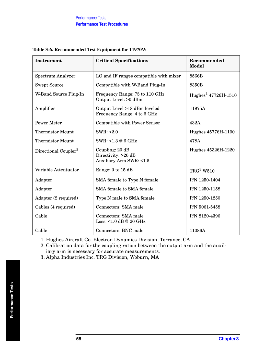
Table 3-6. Recommended Test Equipment for 11970W
Instrument | Critical Specifications | Recommended |
|
| Model |
|
|
|
Spectrum Analyzer | LO and IF ranges compatible with mixer | 8566B |
Swept Source | Compatible with | 8350B |
Frequency Range: 75 to 110 GHz | Hughes1 | |
| Output Level: >0 dBm |
|
Amplifier | Output Level >18 dBm leveled | 11975A |
| Frequency Range: 4 to 6 GHz |
|
Power Meter | Compatible with Power Sensor | 432A |
Thermistor Mount | SWR: <2.0 | Hughes |
Thermistor Mount | SWR: <1.3 @ 6 GHz | 478A |
Directional Coupler2 | Coupling: 20 dB | Hughes |
| Directivity: >20 dB |
|
| Auxiliary Arm SWR: <1.5 |
|
Variable Attentuator | Range: 0 to 15 dB | TRG3 W510 |
Adapter | SMA female to Type N female | P/N |
Adapter | SMA female to SMA female | P/N |
Adapter (2 required) | Type N male to SMA female | P/N |
Cables (4 required) | Connectors: SMA male | P/N |
Cable | Connectors: SMA male | P/N |
| Loss: <1.0 dB @ 20 GHz |
|
Cable | Connectors: BNC male | 11086A |
|
|
|
1.Hughes Aircraft Co. Electron Dynamics Division, Torrance, CA
2.Calibration data for the coupling ration between the output arm and the auxil- iary arm is necessary for accurate measurements.
3.Alpha Industries Inc. TRG Division, Woburn, MA
Performance Tests
56 | Chapter 3 |