Performance Tests
Performance Test Procedures
Performance Test Procedures
Description
Each performance test procedure is contained in a single paragraph. The first entry in each paragraph is the specification for the parameter being measured as described in Table
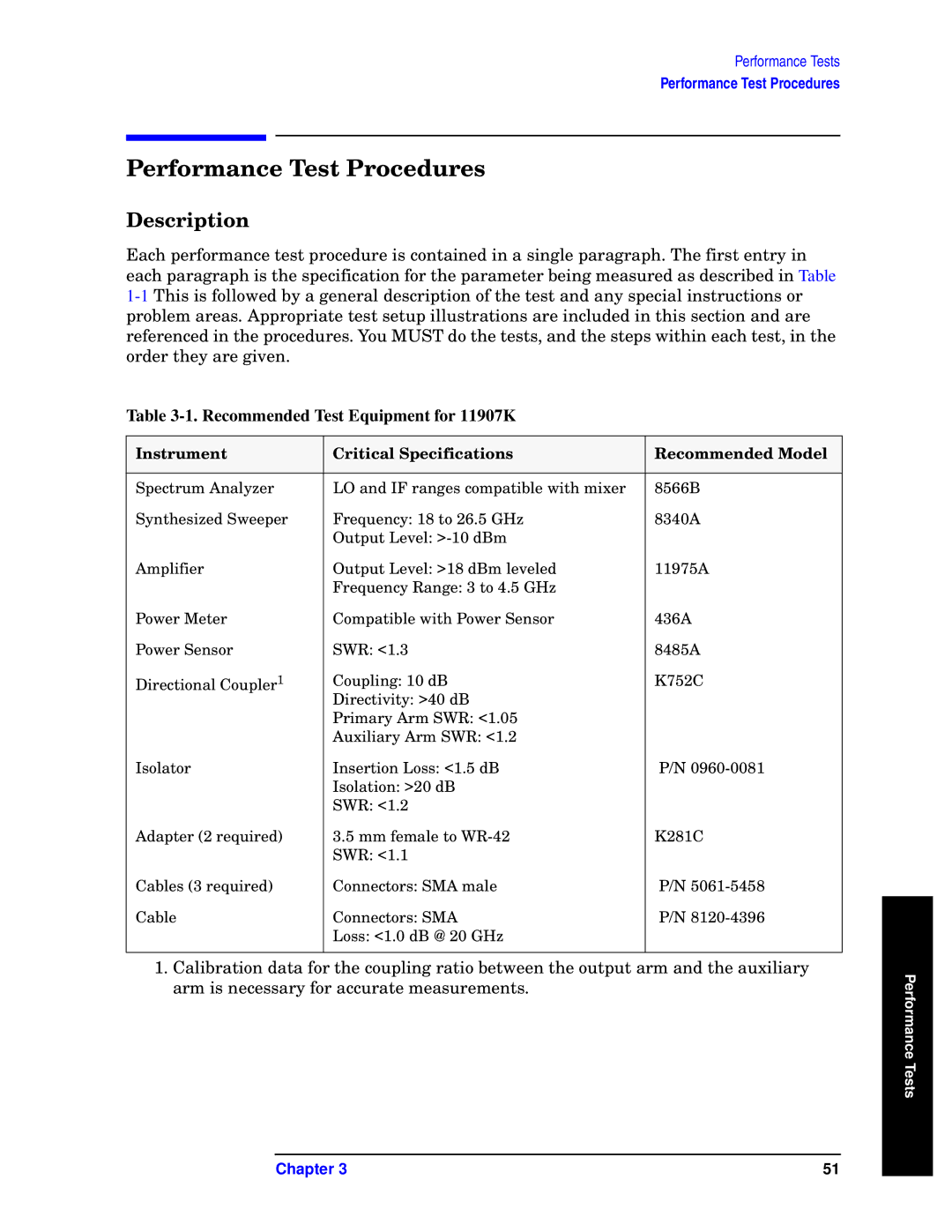
Table 3-1. Recommended Test Equipment for 11907K
Instrument | Critical Specifications | Recommended Model |
|
|
|
Spectrum Analyzer | LO and IF ranges compatible with mixer | 8566B |
Synthesized Sweeper | Frequency: 18 to 26.5 GHz | 8340A |
| Output Level: |
|
Amplifier | Output Level: >18 dBm leveled | 11975A |
| Frequency Range: 3 to 4.5 GHz |
|
Power Meter | Compatible with Power Sensor | 436A |
Power Sensor | SWR: <1.3 | 8485A |
Directional Coupler1 | Coupling: 10 dB | K752C |
| Directivity: >40 dB |
|
| Primary Arm SWR: <1.05 |
|
| Auxiliary Arm SWR: <1.2 |
|
Isolator | Insertion Loss: <1.5 dB | P/N |
| Isolation: >20 dB |
|
| SWR: <1.2 |
|
Adapter (2 required) | 3.5 mm female to | K281C |
| SWR: <1.1 |
|
Cables (3 required) | Connectors: SMA male | P/N |
Cable | Connectors: SMA | P/N |
| Loss: <1.0 dB @ 20 GHz |
|
|
|
|
1. Calibration data for the coupling ratio between the output arm and the auxiliary
arm is necessary for accurate measurements.Performance Tests
Chapter 3 | 51 |