Performance Tests
Performance Test Procedures
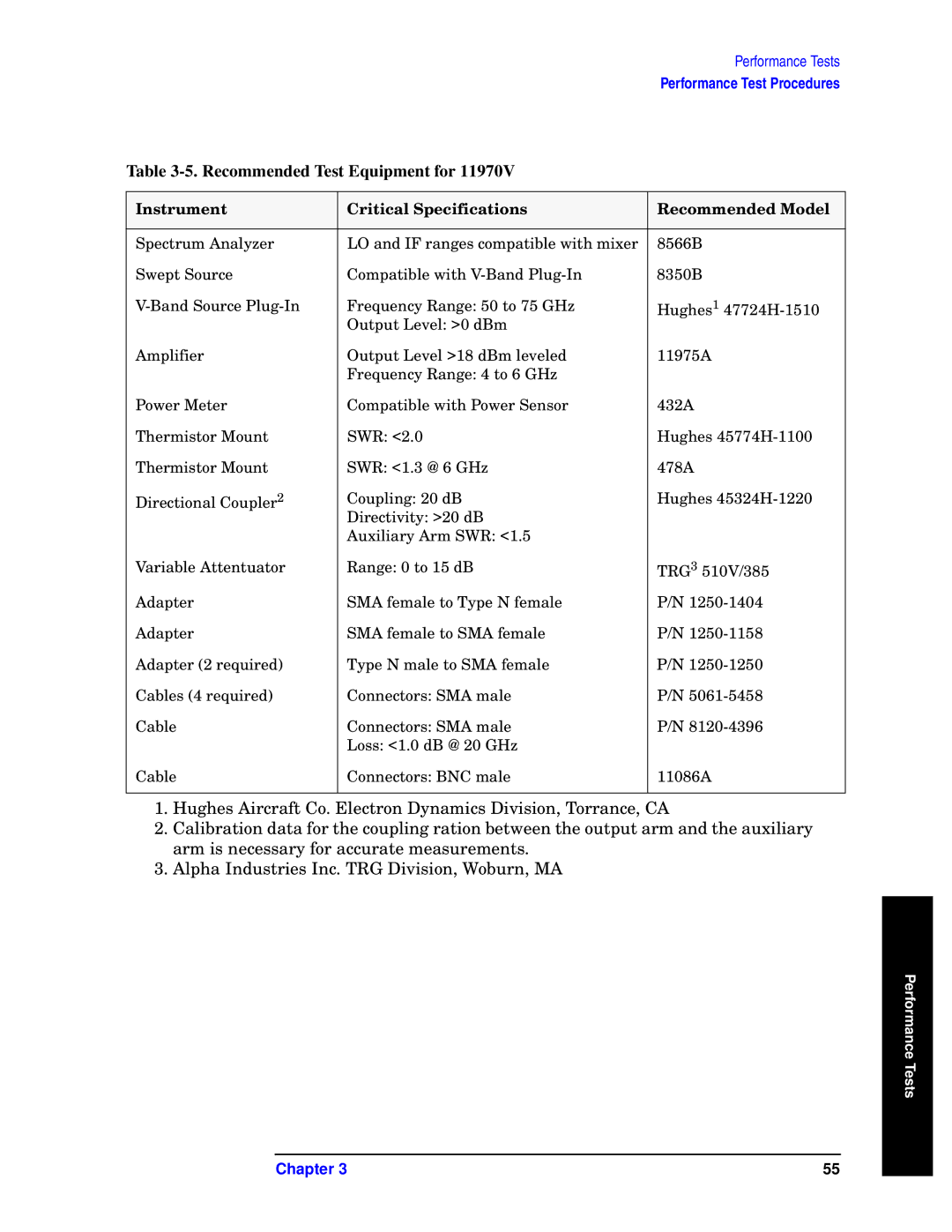
Table 3-5. Recommended Test Equipment for 11970V
Instrument | Critical Specifications | Recommended Model |
|
|
|
Spectrum Analyzer | LO and IF ranges compatible with mixer | 8566B |
Swept Source | Compatible with | 8350B |
Frequency Range: 50 to 75 GHz | Hughes1 | |
| Output Level: >0 dBm |
|
Amplifier | Output Level >18 dBm leveled | 11975A |
| Frequency Range: 4 to 6 GHz |
|
Power Meter | Compatible with Power Sensor | 432A |
Thermistor Mount | SWR: <2.0 | Hughes |
Thermistor Mount | SWR: <1.3 @ 6 GHz | 478A |
Directional Coupler2 | Coupling: 20 dB | Hughes |
| Directivity: >20 dB |
|
| Auxiliary Arm SWR: <1.5 |
|
Variable Attentuator | Range: 0 to 15 dB | TRG3 510V/385 |
Adapter | SMA female to Type N female | P/N |
Adapter | SMA female to SMA female | P/N |
Adapter (2 required) | Type N male to SMA female | P/N |
Cables (4 required) | Connectors: SMA male | P/N |
Cable | Connectors: SMA male | P/N |
| Loss: <1.0 dB @ 20 GHz |
|
Cable | Connectors: BNC male | 11086A |
|
|
|
1.Hughes Aircraft Co. Electron Dynamics Division, Torrance, CA
2.Calibration data for the coupling ration between the output arm and the auxiliary arm is necessary for accurate measurements.
3.Alpha Industries Inc. TRG Division, Woburn, MA
Performance Tests
Chapter 3 | 55 |
