87130A specifications
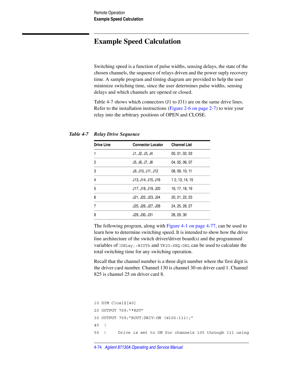
Agilent Technologies 87130A is a highly regarded network analyzer that has been widely adopted in the field of RF and microwave testing. Known for its versatility and precision, the 87130A is designed for evaluating components and devices in various applications, including telecommunications and electronics.One of the main features of the 87130A is its frequency range, which spans from 300 kHz to 3 GHz. This broad spectrum allows engineers to test a wide variety of RF components, including amplifiers, filters, and antennas. The analyzer provides vector network analysis capabilities, enabling users to measure both the magnitude and phase of S-parameters, essential for characterizing components effectively.
The instrument is equipped with a powerful internal calibration capability, which ensures accurate measurements by compensating for test fixture errors and other variables. The built-in electronic calibration options further enhance measurement accuracy and repeatability, giving engineers confidence in their results.
Another notable characteristic of the 87130A is its graphical user interface, which is intuitive and user-friendly. The display provides clear visual representations of measurement data, allowing for easy interpretation and analysis. Users can access a variety of measurement functions, such as gain compression, group delay, and return loss, making it a versatile tool for multi-faceted testing.
The Agilent 87130A employs advanced measurement algorithms that improve speed and accuracy. These enhancements facilitate rapid data acquisition, which is particularly beneficial in production environments where time is critical. The analyzer also supports multiple calibration techniques, including through-reflect-match (TRM) and short-open-load (SOL), catering to diverse testing needs.
Connectivity options are abundant, with GPIB, LAN, and USB interfaces, allowing seamless integration into automated test setups. This modularity supports remote operation, making it easier to incorporate the analyzer into various testing environments.
Overall, Agilent Technologies 87130A stands out for its precision, ease of use, and flexibility in RF and microwave testing applications. Its combination of advanced features and robust performance makes it a staple in laboratories, production lines, and research settings, helping engineers and technicians achieve optimal results in their measurement endeavors.

