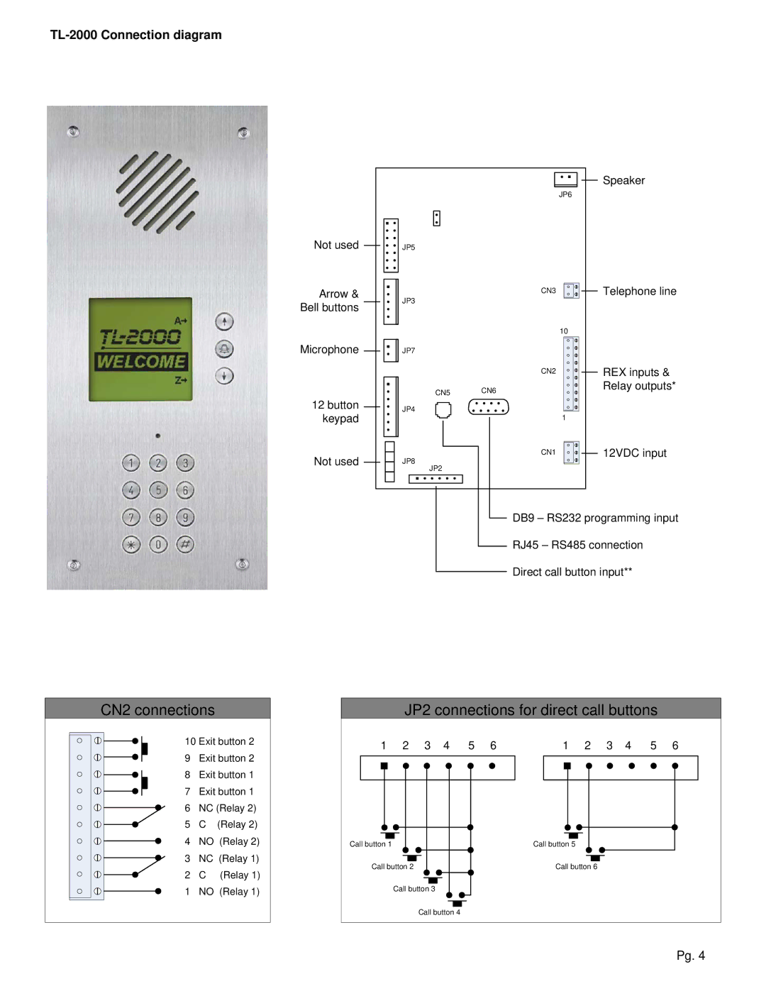
TL-2000 Connection diagram
|
|
| Speaker |
|
|
| JP6 |
Not used | JP5 |
|
|
Arrow & |
| CN3 | Telephone line |
|
|
| |
Bell buttons | JP3 |
|
|
|
|
| |
|
|
| 10 |
Microphone | JP7 |
|
|
|
| CN2 | REX inputs & |
| CN5 | CN6 | Relay outputs* |
|
| ||
12 button | JP4 |
|
|
keypad |
|
| 1 |
Not used | JP8 | CN1 | 12VDC input |
|
| ||
| JP2 |
|
|
|
| DB9 – RS232 programming input | |
|
| RJ45 – RS485 connection | |
|
| Direct call button input** | |
CN2 connections
10 Exit button 2
9 Exit button 2
8 Exit button 1
7 Exit button 1
6 NC (Relay 2)
5 C (Relay 2)
4 NO (Relay 2)
3 NC (Relay 1)
2 C (Relay 1)
1 NO (Relay 1)
JP2 connections for direct call buttons
1 | 2 | 3 | 4 | 5 | 6 | 1 | 2 | 3 | 4 | 5 | 6 | |
|
|
|
|
|
|
|
|
|
|
|
|
|
|
|
|
|
|
|
|
|
|
|
|
|
|
|
|
|
|
|
|
|
|
|
|
|
|
|
|
|
|
|
|
|
|
|
|
|
|
|
|
|
Call button 1 |
|
| Call button 5 | |||||||||||||||||||||||
|
|
|
|
|
|
|
|
|
|
|
|
|
|
|
|
|
|
|
|
|
|
|
|
|
|
|
|
|
|
|
|
|
|
|
|
|
|
|
|
|
|
|
|
|
|
|
|
|
| ||||
Call button 2 |
|
| Call button 6 | |||||||||||||||||||||||
|
|
|
|
|
|
|
|
|
|
|
|
|
|
|
|
|
|
|
|
|
|
|
|
|
|
|
|
|
|
|
|
|
|
|
|
|
|
|
|
|
|
|
|
|
|
| |||||||
|
| Call button 3 |
|
|
|
|
|
|
|
|
|
| ||||||||||||||
|
|
|
|
|
|
|
|
|
|
|
|
|
|
|
|
|
|
|
|
|
| |||||
|
|
|
|
|
|
|
|
|
|
|
|
|
|
|
|
|
|
|
|
| ||||||
|
|
|
|
|
|
| Call button 4 |
|
|
|
|
|
|
|
|
|
| |||||||||
Pg. 4