OPERATION
The electrical power can be “ON” or “OFF” for the emergency controls to work. Using a punch or nail press the gold button to get the movement desired. The electrical wires may be left connected or may be disconnected; the button will operate the function in either case. The code on the wires can be used to identify the valve function.
NOTE: The “Head Tilt Down” control will not operate because of the
The speed of movement is not variable due to the bypass of the “Joystick” function. Post an observer on the boom side of the tractor, out of harms way, to assist with direction of boom movement.
6.1 Maverick Boom Control System
Operating the boom control functions is done so by means of a load sensing electronic over hydraulic system. There are three main areas of that system, the electronic network, instrumentation and the hydraulic components.
System Components
•The hydraulic system
•The electronic network
•The instrumentation
• Operator Interface |
|
The Hydraulic System
The hydraulic components are responsible for transferring mechanical power into hydraulic power. There are two separate hydraulic circuits, the boom circuit, and the mower head circuit.
How the Boom is controlled
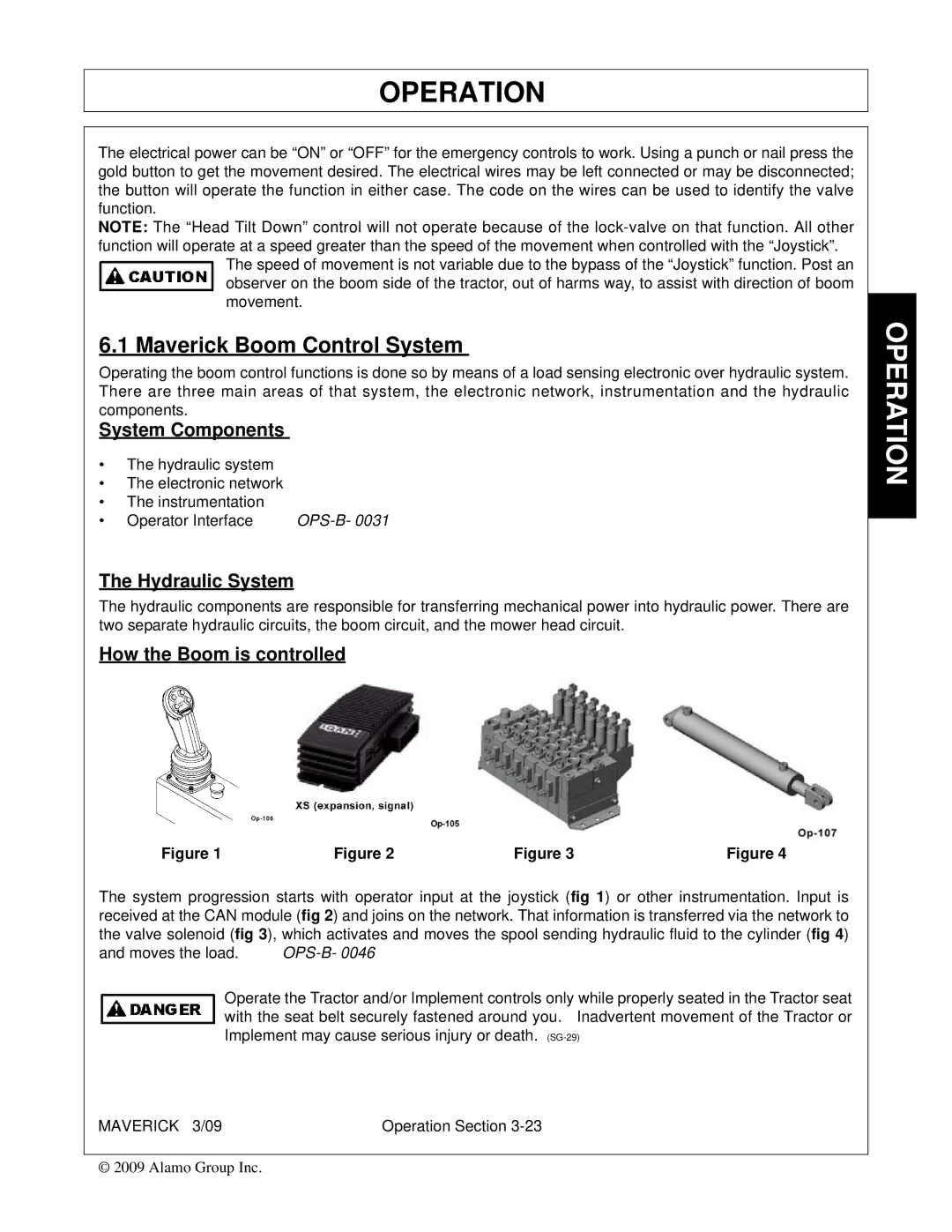
Figure 1Figure 2Figure 3Figure 4
The system progression starts with operator input at the joystick (fig 1) or other instrumentation. Input is received at the CAN module (fig 2) and joins on the network. That information is transferred via the network to the valve solenoid (fig 3), which activates and moves the spool sending hydraulic fluid to the cylinder (fig 4)
and moves the load. |
|
Operate the Tractor and/or Implement controls only while properly seated in the Tractor seat with the seat belt securely fastened around you. Inadvertent movement of the Tractor or Implement may cause serious injury or death.
MAVERICK 3/09 | Operation Section |
© 2009 Alamo Group Inc.
