Configuring OSPF | OSPF Application Example |
|
|
|
|
Step 1: Prepare the Routers
The first step is to create the VLANs on each router, add an IP interface to the VLAN, assign a port to the VLAN, and assign a router identification number to the routers. For the backbone, the network design in this case uses slot 2, port 1 as the egress port and slot 2, port 2 as ingress port on each router. Router 1 connects to Router 2, Router 2 connects to Router 3, and Router 3 connects to Router 1 using 10/100 Ethernet cables.
Note. The ports will be statically assigned to the router, as a VLAN must have a physical port assigned to it in order for the router port to function. However, the router could be set up in such a way that mobile ports are dynamically assigned to VLANs using VLAN rules. See the chapter titled “Defining VLAN Rules” in the OmniSwitch 6600 Family Network Configuration Guide.
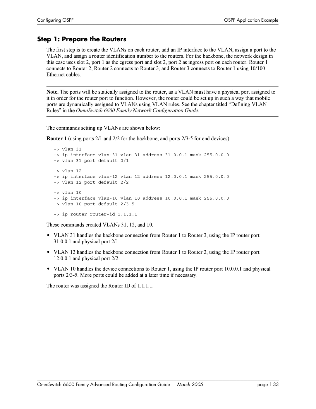
The commands setting up VLANs are shown below:
Router 1 (using ports 2/1 and 2/2 for the backbone, and ports
| |
default 2/1 | |
| |
default 2/2 | |
| |
default |
These commands created VLANs 31, 12, and 10.
•VLAN 31 handles the backbone connection from Router 1 to Router 3, using the IP router port
31.0.0.1and physical port 2/1.
•VLAN 12 handles the backbone connection from Router 1 to Router 2, using the IP router port
12.0.0.1and physical port 2/2.
•VLAN 10 handles the device connections to Router 1, using the IP router port 10.0.0.1 and physical ports
The router was assigned the Router ID of 1.1.1.1.
OmniSwitch 6600 Family Advanced Routing Configuration Guide March 2005 | page |
