OSPF Application ExampleConfiguring OSPF
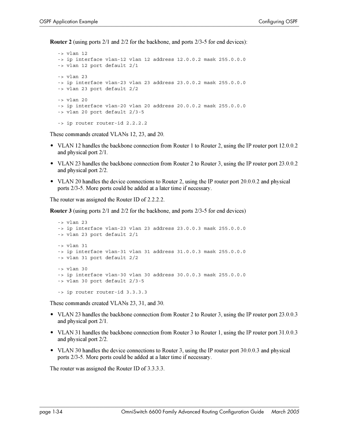
Router 2 (using ports 2/1 and 2/2 for the backbone, and ports
| |
default 2/1 | |
| |
default 2/2 | |
| |
default |
These commands created VLANs 12, 23, and 20.
•VLAN 12 handles the backbone connection from Router 1 to Router 2, using the IP router port 12.0.0.2 and physical port 2/1.
•VLAN 23 handles the backbone connection from Router 2 to Router 3, using the IP router port 23.0.0.2 and physical port 2/2.
•VLAN 20 handles the device connections to Router 2, using the IP router port 20.0.0.2 and physical ports
The router was assigned the Router ID of 2.2.2.2.
Router 3 (using ports 2/1 and 2/2 for the backbone, and ports
| |
default 2/1 | |
| |
default 2/2 | |
| |
default |
These commands created VLANs 23, 31, and 30.
•VLAN 23 handles the backbone connection from Router 2 to Router 3, using the IP router port 23.0.0.3 and physical port 2/1.
•VLAN 31 handles the backbone connection from Router 3 to Router 1, using the IP router port 31.0.0.3 and physical port 2/2.
•VLAN 30 handles the device connections to Router 3, using the IP router port 30.0.0.3 and physical ports
The router was assigned the Router ID of 3.3.3.3.
page | OmniSwitch 6600 Family Advanced Routing Configuration Guide March 2005 |
