Overview
These devices can be used in
These units are sold in pairs with the
The
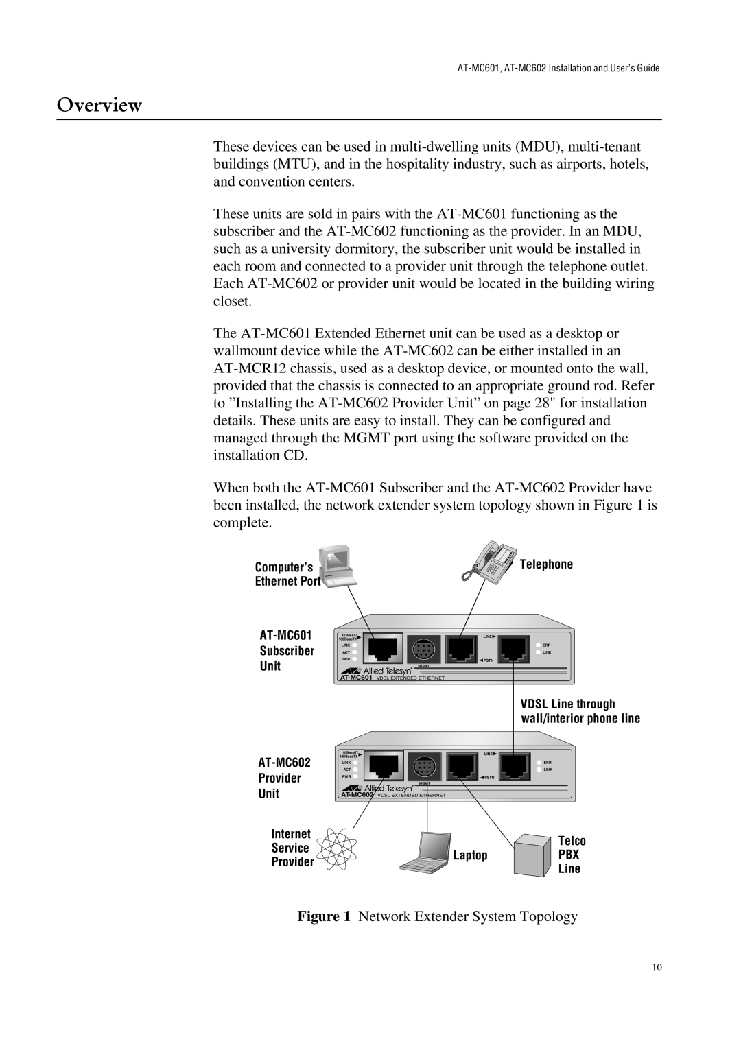
When both the
Computer’s | Telephone |
Ethernet Port |
|
AT-MC601
Subscriber
Unit
AT-MC602
Provider
Unit
10BaseT/
100BaseTX
LINK
ACT
PWR
MGMT
10BaseT/
100BaseTX
LINK
ACT
PWR
MGMT
LINE |
ERR |
LINK |
PSTN |
VDSL Line through |
wall/interior phone line |
LINE |
ERR |
LINK |
PSTN |
Internet |
| Telco | |
Service |
| ||
Laptop | PBX | ||
Provider | |||
| Line | ||
|
|
Figure 1 Network Extender System Topology
10