REV. E
American Panel Corporation
E-mail service@americanpanel.com
USER’S MANUAL
INSTALLATION OF REMOTE UNITS
CONTROLLER FEATURES
REQUIREMENTS TO BE MET DURING INSTALLATION 8 STEPS
INSTALLATION AT THE SAME LEVEL
MAINTENANCE
PREPARING AND USING THE OPTIONAL PRINTER
MAINTENANCE AND CLEANING
CLEANING THE CONDENSER
CONTROLLER FEATURES
INTRODUCTION
OPERATING MODES
OPERATING CYCLES
PRINTER OPTIONAL
PC CONNECTION OPTIONAL
REQUIREMENTS TO BE MET DURING INSTALLATION 8 STEPS
INSTALLATION OF REMOTE UNITS
INSTALLATION AT THE SAME LEVEL
COMPRESSOR
CONNECTION PIPING FOR REMOTE CONDENSING UNITS
INSTALLATION AT DIFFERENT LEVELS
INSTALLATION
INSTALLATION
DIMENSIONS
WARNINGS
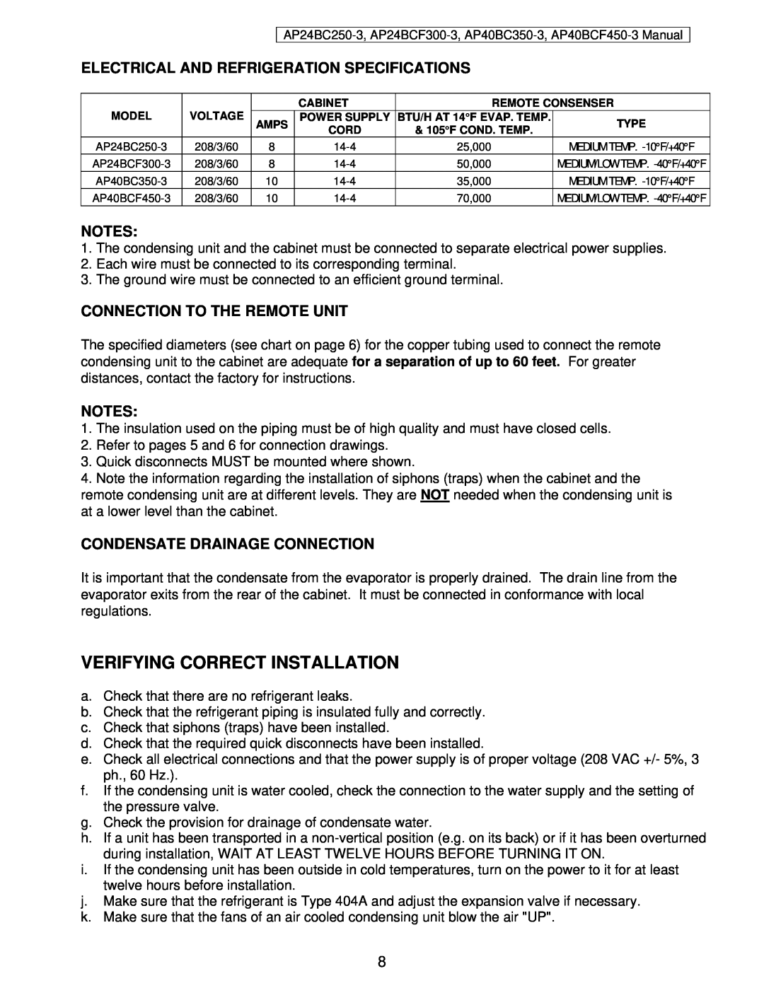
ELECTRICAL AND REFRIGERATION SPECIFICATIONS
VERIFYING CORRECT INSTALLATION
CONNECTION TO THE REMOTE UNIT
CONDENSATE DRAINAGE CONNECTION
SPACES AROUND THE CABINET
STARTING & TESTING THE UNIT
BLAST CHILLING
USING THE HURRICHILL TECHNOLOGY
SHOCK FREEZING
SOFT CHILL CYCLE
PANNING AND LOADING
PANNING
LOADING
CONTROL PANEL FOR MODELS AP24 & AP40 BLAST CHILLERS / SHOCK FREEZERS
KEY COMBINATIONS
KEYBOARD KEYS
ON/OFF & START/STOP
PROGRAMMING KEYS
If the entered password is wrong the display will show
c. Enter the default password by pressing, in order, the
PROGRAMMING
1. INITIAL PROGRAMMING
The high air alarm temperature should be left at
The low air alarm temperature should be left at
The high food alarm temperature should be left at
The P.C. baud rate should be left at
The low food alarm temperature should be left at
YES for shock freezers AP24BCF300-3, AP40BCF450-3
NO for blast chillers AP24BC250-3, AP40BC350-3 and go to step r
2. PROGRAMMING THE CYCLES
AUTOMATIC HARD CYCLE PARAMETERS PROGRAMMING
AUTOMATIC SOFT CYCLE PARAMETERS PROGRAMMING
k. To change the temperature, press
AUTOMATIC SHOCK CYCLE PARAMETERS PROGRAMMING
then press
p. To change the temperature, press
UV LIGHT CYCLE PARAMETERS PROGRAMMING
HEATED PROBE CYCLE PARAMETERS PROGRAMMING
DEFROST CYCLE PARAMETERS PROGRAMMING
The defrost type must be left AIR FLOW
aa. Press
gg. Press
MANUAL SOFT CYCLE PARAMETERS PROGRAMMING
The LED for SOFT will be steady
hh. To change the temperature, press
MANUAL HARD CYCLE PARAMETERS PROGRAMMING
MANUAL SHOCK CYCLE PARAMETERS PROGRAMMING
3. RECIPE NAME PROGRAMMING
1. AUTOMATIC MODE - SOFT CHILL
OPERATION
2. MANUAL MODE - SOFT CHILL
alternating with
alternating
3. HARD CHILL CYCLE
5. UV STERILIZATION CYCLE
4. SHOCK FREEZE CYCLE
6. DEFROST CYCLE
a. To perform a UV cycle remove all food, then press
b. Open the door
7. HEATED FOOD PROBE
c. Press the
defrost cycle
OTE To stop any cycle before it has finished, press START/STOP
8. PREPARING AND USING THE OPTIONAL PRINTER
NOTE The optional printer is delivered fully installed
d. Enter your password, then press
PRINTER
9. TO CLEAR DATA
LOADING A ROLL OF PAPER
MAINTENANCE
REMOVING A ROLL OF PAPER
OPERATING THE PRINTER
MAINTENANCE AND CLEANING
CLEANING THE CONDENSER
REPLACING THE RIBBON WITH PAPER IN THE PRINTER
CLEANING
WIRING DIAGRAMS
COMPARTMENT
DO NOT USE ABRASIVES, SOLVENTS
AP24BC250-3, AP24BCF300-3, AP40BC350-3, AP40BCF450-3 Manual
AP24BC250-3, AP24BCF300-3, AP40BC350-3, AP40BCF450-3 Manual
AP24BC250-3, AP24BCF300-3, AP40BC350-3, AP40BCF450-3 Manual
COMPUTER CONNECTION
PARTS LIST
PART #
DESCRIPTION
installing contractor. It is not covered by this Warranty
STANDARD WARRANTY
AMERICAN PANEL CORP
BLAST CHILLERS / SHOCK FREEZERS ONLY
ORDERING PRINTER SUPPLIES RIBBON & PAPER
