During the self-test, the unit briefly operates the loads on-battery (the on-battery LED comes on). If the unit passes the self-test, it returns to on-line operation. The on-battery LED goes off and the on-line LED goes on steady.
If the unit fails the self-test it immediately returns to on-line operation and lights the replace bat- tery LED. The loads are not affected. Recharge the battery overnight and perform the self-test again. If the replace battery LED is still on, see section 10 for information on replacing the battery.
5.4 Load Bar Graph
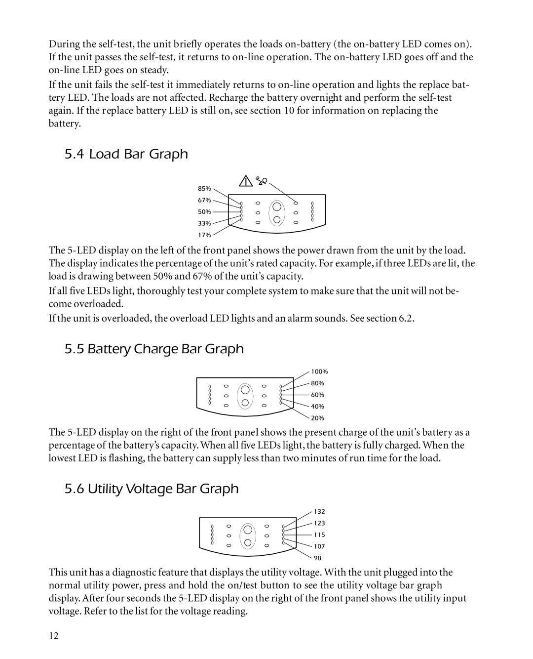
The 5-LED display on the left of the front panel shows the power drawn from the unit by the load. The display indicates the percentage of the unit’s rated capacity. For example, if three LEDs are lit, the load is drawing between 50% and 67% of the unit’s capacity.
If all five LEDs light, thoroughly test your complete system to make sure that the unit will not be- come overloaded.
If the unit is overloaded, the overload LED lights and an alarm sounds. See section 6.2.
5.5 Battery Charge Bar Graph
The 5-LED display on the right of the front panel shows the present charge of the unit’s battery as a percentage of the battery’s capacity. When all five LEDs light, the battery is fully charged. When the lowest LED is flashing, the battery can supply less than two minutes of run time for the load.
5.6 Utility Voltage Bar Graph
This unit has a diagnostic feature that displays the utility voltage. With the unit plugged into the normal utility power, press and hold the on/test button to see the utility voltage bar graph display. After four seconds the 5-LED display on the right of the front panel shows the utility input voltage. Refer to the list for the voltage reading.

