Appendix
9.0Appendix
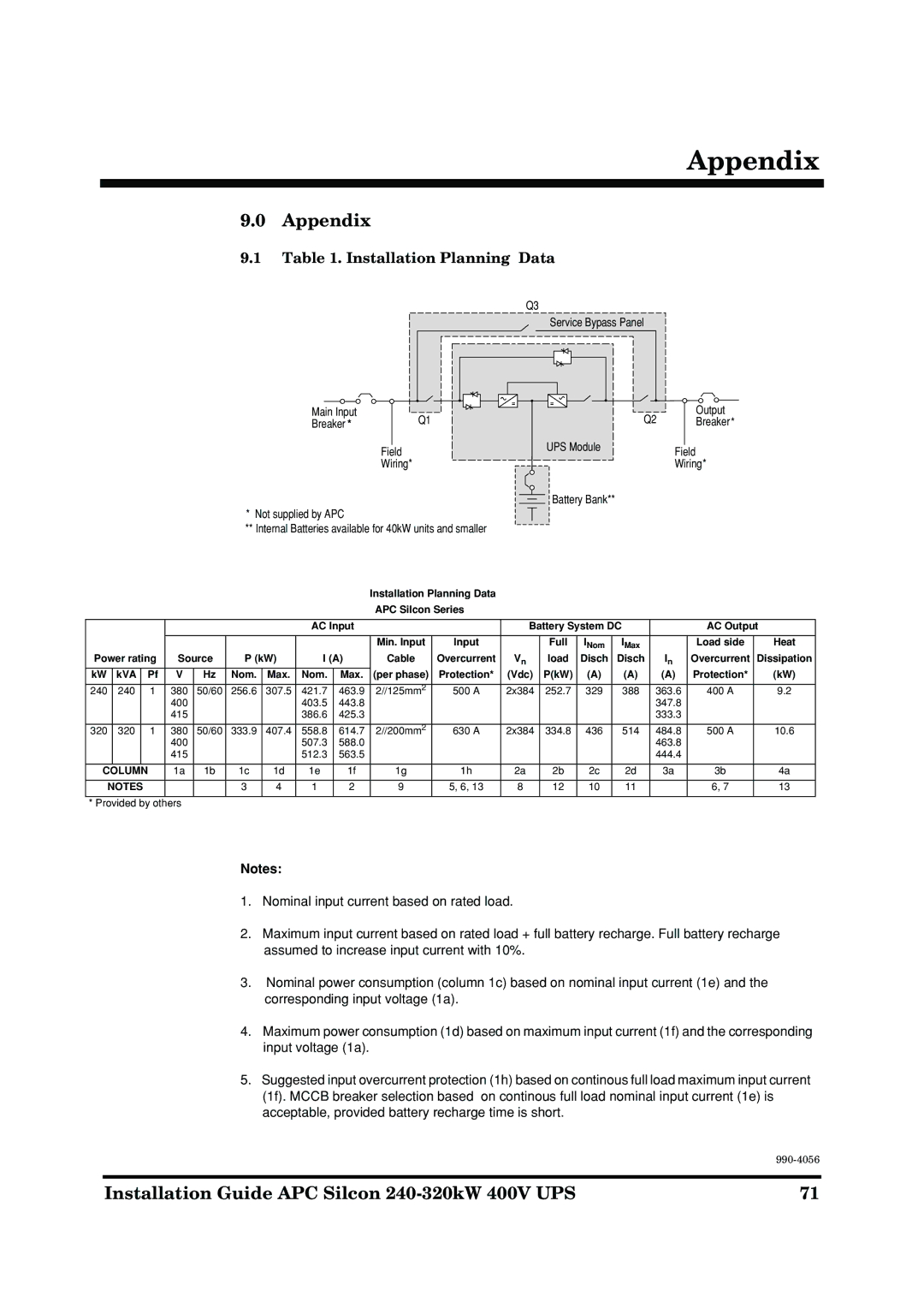
9.1Table 1. Installation Planning Data
|
| Q3 |
|
|
| Service Bypass Panel |
|
Main Input | Q1 | Q2 | Output |
Breaker * | Breaker* | ||
| Field | UPS Module | Field |
|
| ||
| Wiring* |
| Wiring* |
|
| Battery Bank** |
|
*Not supplied by APC
**Internal Batteries available for 40kW units and smaller
Installation Planning Data
APC Silcon Series
|
|
|
|
|
|
|
|
| AC Input |
|
| Battery System DC |
| AC Output | |||||
|
|
|
|
|
|
|
|
|
|
|
|
|
|
|
|
|
|
|
|
|
|
|
|
|
|
|
|
|
|
| Min. Input | Input |
| Full | INom | IMax |
| Load side | Heat |
Power rating | Source | P (kW) | I (A) | Cable | Overcurrent | Vn | load | Disch | Disch | In | Overcurrent | Dissipation | |||||||
kW |
| kVA |
| Pf | V | Hz | Nom. | Max. | Nom. | Max. | (per phase) | Protection* | (Vdc) | P(kW) | (A) | (A) | (A) | Protection* | (kW) |
|
|
|
|
|
|
|
|
|
|
|
|
|
|
|
|
|
|
|
|
240 |
| 240 |
| 1 | 380 | 50/60 | 256.6 | 307.5 | 421.7 | 463.9 | 2//125mm2 | 500 A | 2x384 | 252.7 | 329 | 388 | 363.6 | 400 A | 9.2 |
|
|
|
|
| 400 |
|
|
| 403.5 | 443.8 |
|
|
|
|
|
| 347.8 |
|
|
|
|
|
|
| 415 |
|
|
| 386.6 | 425.3 |
|
|
|
|
|
| 333.3 |
|
|
|
|
|
|
|
|
|
|
|
|
|
|
|
|
|
|
|
|
|
|
320 |
| 320 |
| 1 | 380 | 50/60 | 333.9 | 407.4 | 558.8 | 614.7 | 2//200mm2 | 630 A | 2x384 | 334.8 | 436 | 514 | 484.8 | 500 A | 10.6 |
|
|
|
|
| 400 |
|
|
| 507.3 | 588.0 |
|
|
|
|
|
| 463.8 |
|
|
|
|
|
|
| 415 |
|
|
| 512.3 | 563.5 |
|
|
|
|
|
| 444.4 |
|
|
|
|
|
|
|
|
|
|
|
|
|
|
|
|
|
|
|
| ||
| COLUMN |
| 1a | 1b | 1c | 1d | 1e | 1f | 1g | 1h | 2a | 2b | 2c | 2d | 3a | 3b | 4a | ||
|
|
|
|
|
|
|
|
|
|
|
|
|
|
|
|
|
| ||
| NOTES |
|
|
| 3 | 4 | 1 | 2 | 9 | 5, 6, 13 | 8 | 12 | 10 | 11 |
| 6, 7 | 13 | ||
|
|
|
|
|
|
|
|
|
|
|
|
|
|
|
| ||||
* Provided by others |
|
|
|
|
|
|
|
|
|
|
|
|
|
| |||||
Notes:
1.Nominal input current based on rated load.
2.Maximum input current based on rated load + full battery recharge. Full battery recharge assumed to increase input current with 10%.
3.Nominal power consumption (column 1c) based on nominal input current (1e) and the corresponding input voltage (1a).
4.Maximum power consumption (1d) based on maximum input current (1f) and the corresponding input voltage (1a).
5.Suggested input overcurrent protection (1h) based on continous full load maximum input current (1f). MCCB breaker selection based on continous full load nominal input current (1e) is acceptable, provided battery recharge time is short.
Installation Guide APC Silcon | 71 |