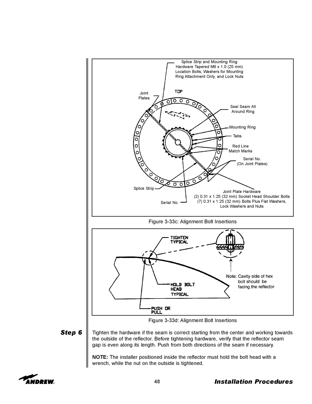
Splice Strip and Mounting Ring
Hardware Tapered M6 x 1.0 (25 mm) Location Bolts, Washers for Mounting Ring Attachment Only, and Lock Nuts
Joint
Plates
Splice Strip
Seal Seam All
Around Ring
Mounting Ring
Tabs
Red Line
Match Marks
Serial No.
(On Joint Plates)
Joint Plate Hardware
Step 6
(2) 0.31 x 1.25 (32 mm) Socket Head Shoulder Bolts
Serial No. (7) 0.31 x 1.25 (32 mm) Bolts Plus Flat Washers,
Lock Washers and Nuts
Figure 3-33c: Alignment Bolt Insertions
Figure 3-33d: Alignment Bolt Insertions
Tighten the hardware if the seam is correct starting from the center and working towards the outside of the reflector. Before tightening hardware, verify that the reflector seam gap is even along its length. Push from both directions of the seam if necessary.
NOTE: The installer positioned inside the reflector must hold the bolt head with a wrench, while the nut on the outside is tightened.
48 | Installation Procedures |