Step 2
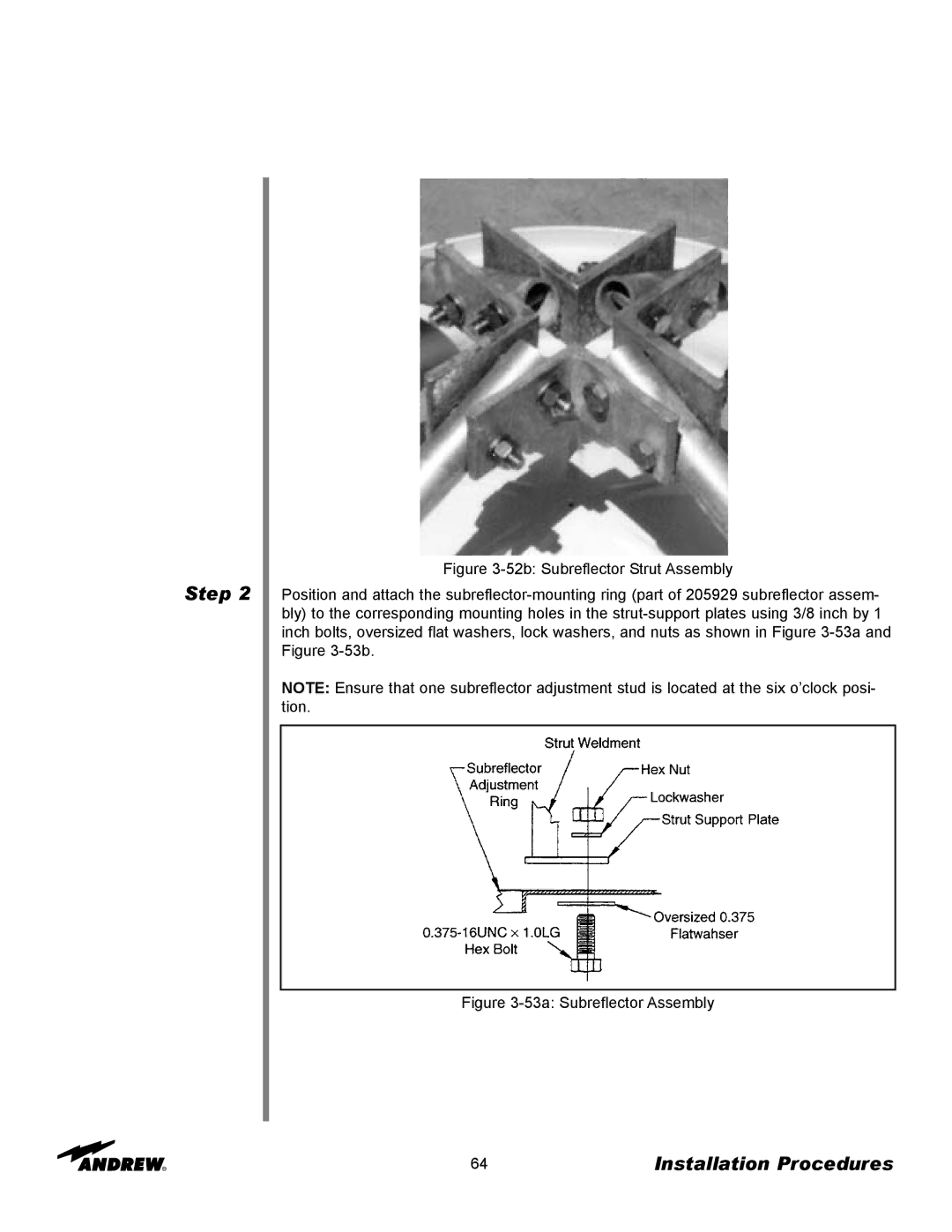
Figure 3-52b: Subreflector Strut Assembly
Position and attach the subreflector-mounting ring (part of 205929 subreflector assem- bly) to the corresponding mounting holes in the strut-support plates using 3/8 inch by 1 inch bolts, oversized flat washers, lock washers, and nuts as shown in Figure 3-53a and Figure 3-53b.
NOTE: Ensure that one subreflector adjustment stud is located at the six o’clock posi- tion.
Figure 3-53a: Subreflector Assembly
64 | Installation Procedures |
