3.3
POWER SWITCH / RESET SWITCH / HARD DISK DRIVE LED CONNECTORS
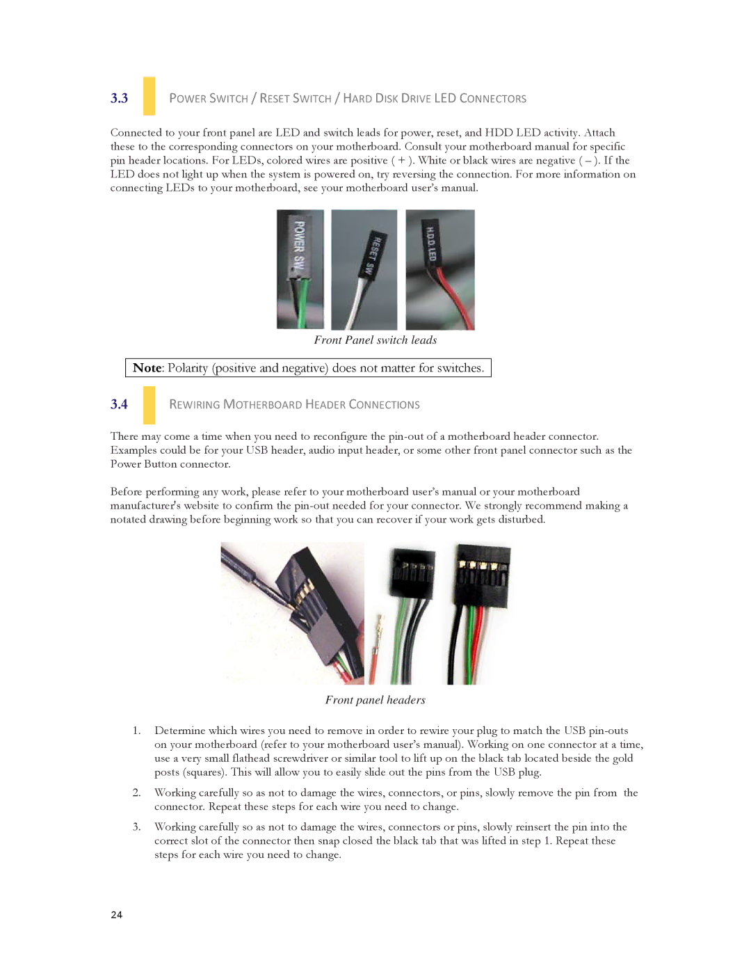
Connected to your front panel are LED and switch leads for power, reset, and HDD LED activity. Attach these to the corresponding connectors on your motherboard. Consult your motherboard manual for specific pin header locations. For LEDs, colored wires are positive ( + ). White or black wires are negative ( – ). If the LED does not light up when the system is powered on, try reversing the connection. For more information on connecting LEDs to your motherboard, see your motherboard user’s manual.
Front Panel switch leads
Note: Polarity (positive and negative) does not matter for switches.
3.4
REWIRING MOTHERBOARD HEADER CONNECTIONS
There may come a time when you need to reconfigure the
Before performing any work, please refer to your motherboard user’s manual or your motherboard manufacturer's website to confirm the
Front panel headers
1.Determine which wires you need to remove in order to rewire your plug to match the USB
2.Working carefully so as not to damage the wires, connectors, or pins, slowly remove the pin from the connector. Repeat these steps for each wire you need to change.
3.Working carefully so as not to damage the wires, connectors or pins, slowly reinsert the pin into the correct slot of the connector then snap closed the black tab that was lifted in step 1. Repeat these steps for each wire you need to change.
24