If there are other effective earth connections, the protective conductors must be connected to such points when it is possible. It may be necessary to earth at additional points to ensure that the potentials of protective conductors remain as close as possible to that of earth in case of a fault.
Additional requirements for generating sets (IEC 60364-5-55 551.4.2)
To be used when the generating set provides a switched alternative to the public supply.
Protection by automatic disconnection of supply must not rely on the connection to the earthed points of the public supply system when the generator is operating as a switched alternative to a TN system. A suitable earth electrode must be provided.
Protective devices in TN systems
The following protective devices are recognized in TN systems:
•Overcurrent protective devices
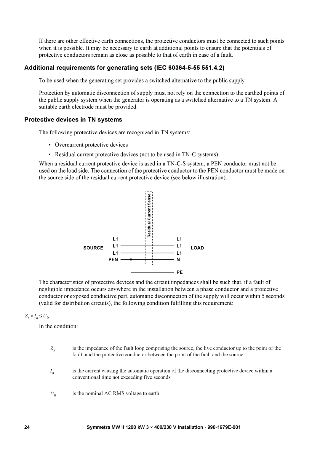
•Residual current protective devices (not to be used in
When a residual current protective device is used in a
L1
SOURCE L1 L1
PEN
| ResidualCurrent Sense |
| |
|
| L1 |
|
|
|
| |
|
| L1 | LOAD |
|
| ||
|
| L1 | |
|
|
| |
|
|
| |
|
| N |
|
|
|
| |
|
| PE |
|
|
|
| |
The characteristics of protective devices and the circuit impedances shall be such that, if a fault of negligible impedance occurs anywhere in the installation between a phase conductor and a protective conductor or exposed conductive part, automatic disconnection of the supply will occur within 5 seconds (valid for distribution circuits), the following condition fulfilling this requirement:
Zs ⋅ Ia ≤ U0
In the condition:
Zs | is the impedance of the fault loop comprising the source, the live conductor up to the point of the |
| fault, and the protective conductor between the point of the fault and the source |
Ia | is the current causing the automatic operation of the disconnecting protective device within a |
| conventional time not exceeding five seconds |
U0 | is the nominal AC RMS voltage to earth |
24 | Symmetra MW II 1200 kW 3 × 400/230 V Installation - |