28
Symmetra MW II 1200 kW 3 × 400/230 V Installation -
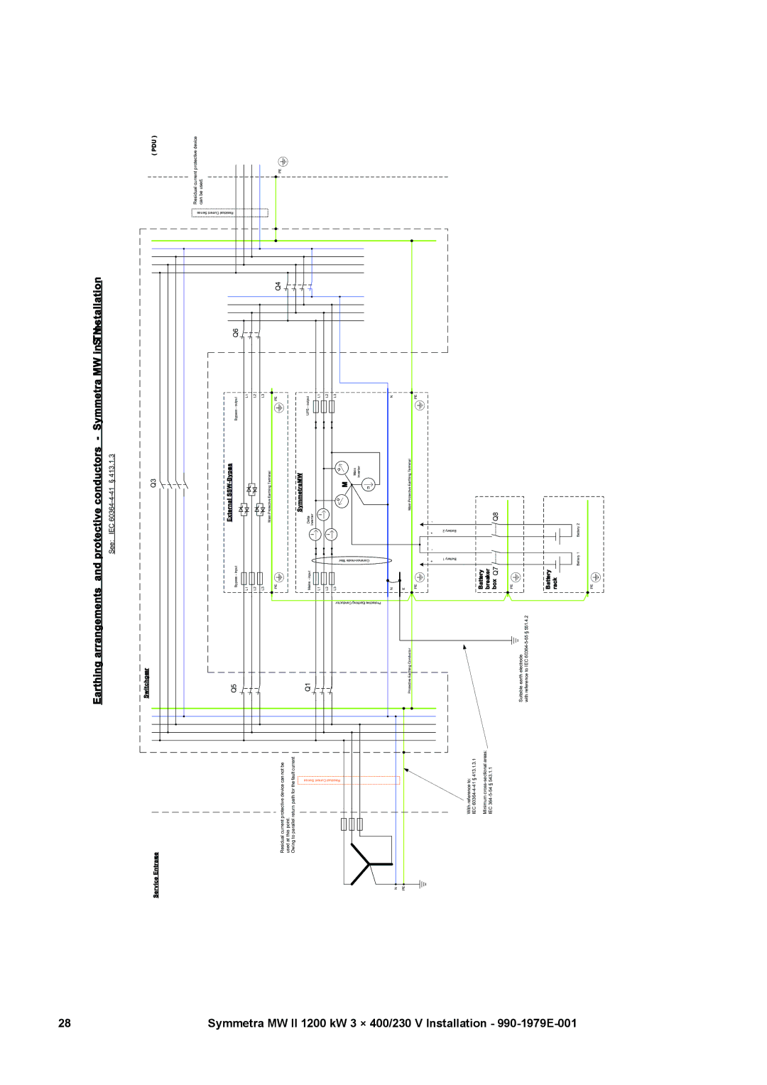
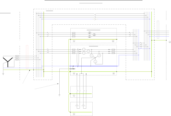
Service Entrance
Residual current protective device can not be used at this point.
Owing to parallel return path for the fault current
Residual Current Sense
N ![]()
PE ![]()
With reference to:
IEC
Minimum
IEC
Earthing arrangements and protective conductors - Symmetra MW inSTNinstallation-
|
| See: | IEC | § 413.1.3 |
|
|
| |
Switchgear |
|
|
|
|
|
|
|
|
|
|
|
| Q3 |
|
| ( PDU ) | |
|
|
|
|
|
|
| Residual Current Sense | Residual current protective device |
|
|
|
|
|
|
| can be used. | |
Q5 |
|
|
| External | Q6 |
| ||
Bypass - input |
|
|
| Bypass - output |
|
| ||
|
|
|
|
|
| |||
| L1 |
|
|
| L1 |
|
|
|
| L2 |
|
|
| L2 |
|
|
|
| L3 |
|
|
| L3 |
|
|
|
|
|
|
| Main Protective Earthing Terminal |
|
|
| |
| PE |
|
|
| PE | Q4 |
|
|
|
|
|
|
|
|
| PE | |
|
|
|
| SymmetraMW |
|
|
| |
Q1 | Mains - input |
| i | Delta | UPS - output |
|
|
|
|
|
| Inverter |
|
|
|
| |
| L1 |
|
| i | L1 |
|
|
|
| L2 |
| i |
| L2 |
|
|
|
|
|
|
|
|
|
|
| |
EarthingProtectiveConductor | L3 |
|
| u | L3 |
|
|
|
|
| u |
|
|
| |||
|
|
|
| u |
|
|
|
|
|
|
|
| M |
|
|
| |
|
|
|
|
| Main |
|
|
|
|
|
|
|
| inverter |
|
|
|
| N |
|
|
| N |
|
|
|
| E |
|
|
|
|
|
|
|
Protective Earthing Conductor |
|
|
| Main Protective Earthing Terminal |
|
|
| |
| PE |
|
|
| PE |
|
|
|
| + | - | + | - |
|
|
|
|
| Battery 1 |
|
| Battery 2 |
|
|
|
|
| Battery |
|
|
|
|
|
|
|
| breaker |
|
|
|
|
|
|
|
| box Q7 |
|
| Q8 |
|
|
|
|
| PE |
|
|
|
|
|
|
|
Suitable earth electrode |
|
|
|
|
|
|
|
|
with reference to IEC |
|
|
|
|
|
|
|
|
| Battery |
|
|
|
|
|
|
|
| rack |
|
|
|
|
|
|
|
| Battery 1 | Battery 2 |
|
|
|
| ||
| PE |
|
|
|
|
|
|
|