Symmetra MW II 1200 kW 3 × 400/230 V Installation -
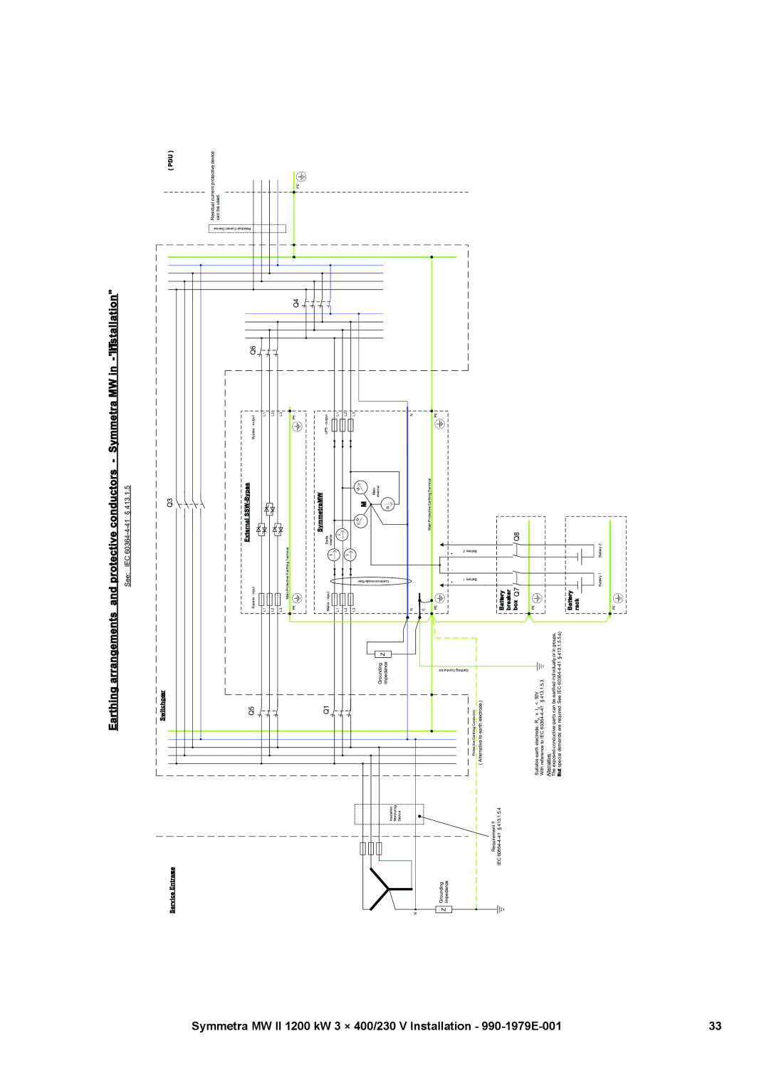
Earthing arrangements and protective conductors - Symmetra MW in
|
|
|
|
| See: |
| IEC | § 413.1.5 |
|
|
| |
|
| Switchgear |
|
|
|
|
|
|
|
|
| |
Service Entrance |
|
|
|
|
|
|
| Q3 |
|
| ( PDU ) | |
|
|
|
|
|
|
|
|
|
|
| ||
|
|
|
|
|
|
|
|
|
|
| Residual Current Sense | Residual current protective device |
|
|
|
|
|
|
|
|
|
|
| can be used. | |
|
| Q5 |
|
|
|
|
| External | Q6 |
| ||
|
|
|
| Bypass - input |
|
|
| Bypass - output |
|
| ||
|
|
|
|
|
|
|
|
|
| |||
|
|
|
|
| L1 |
|
|
| L1 |
|
|
|
|
|
|
|
| L2 |
|
|
| L2 |
|
|
|
|
|
|
|
| L3 |
|
|
| L3 |
|
|
|
|
|
|
|
| Main Protective Earthing Terminal |
|
|
|
|
| ||
|
|
|
|
| PE |
|
|
| PE | Q4 |
|
|
|
|
|
|
|
|
|
|
|
|
| PE | |
|
|
|
|
|
|
|
| SymmetraMW |
|
|
| |
|
| Q1 |
|
| Mains - input |
| i | Delta | UPS - output |
|
|
|
|
|
|
|
|
|
| Inverter |
|
|
|
| |
|
|
|
|
| L1 |
|
| i | L1 |
|
|
|
|
|
|
|
|
|
|
|
|
|
|
| |
|
|
|
|
| L2 |
| i |
| L2 |
|
|
|
|
|
|
|
|
|
|
|
|
|
|
| |
|
|
|
|
| L3 |
|
|
| L3 |
|
|
|
|
|
|
|
| filter |
|
| u | u |
|
|
|
|
|
|
|
|
|
|
| M |
|
|
| |
|
|
|
|
|
|
|
|
|
|
| ||
|
|
|
|
|
|
|
| u |
|
|
| |
|
|
|
|
|
|
|
|
| Main |
|
|
|
|
|
| Grounding |
|
|
|
|
| inverter |
|
|
|
|
|
| Z |
|
|
|
|
|
|
|
| |
|
|
| impedance |
|
|
|
|
|
|
|
| |
|
| Insulation |
|
|
|
|
|
|
|
|
|
|
|
| Monitoring |
|
|
|
|
|
|
|
|
|
|
|
| Device |
|
|
|
|
|
|
|
|
|
|
|
|
|
|
| N |
|
|
| N |
|
|
|
N |
|
|
|
|
|
|
|
|
|
|
|
|
|
|
|
|
| E |
|
|
|
|
|
|
|
|
|
|
|
|
|
|
| Main Protective Earthing Terminal |
|
|
| |
|
| Protective Earthing Conductor | ConductorEarthing |
| PE |
| 2Battery |
| PE |
|
|
|
Z | Grounding |
| 1Battery |
|
|
|
|
|
| |||
| impedance |
|
|
|
|
|
|
|
|
|
|
|
|
|
|
|
| + | - | + | - |
|
|
|
|
|
| ( Alternative to earth electrode ) |
|
|
|
|
|
|
|
|
| |
| Requirement !! |
|
|
|
|
|
|
|
|
|
| |
| IEC | § 413.1.5.4 |
|
| Battery |
|
|
|
|
|
|
|
|
|
|
|
|
|
|
|
|
|
|
| |
|
|
|
|
| breaker |
|
|
|
|
|
|
|
|
|
|
|
| box Q7 |
|
| Q8 |
|
|
|
|
|
| Suitable earth electrode: RA x Id | < 50V |
| PE |
|
|
|
|
|
|
|
|
|
|
|
|
|
|
|
|
|
| ||
|
| With reference to IEC | § 413.1.5.3 |
|
|
|
|
|
|
|
|
|
|
| Alternative: |
|
|
|
|
|
|
|
|
|
|
|
| The |
|
|
|
|
|
|
|
| ||
|
| But special demands are required. See IEC |
|
|
|
|
|
|
|
| ||
|
|
|
|
| Battery |
|
|
|
|
|
|
|
|
|
|
|
| rack |
|
|
|
|
|
|
|
|
|
|
|
| Battery 1 |
| Battery 2 |
|
|
|
| |
|
|
|
|
| PE |
|
|
|
|
|
|
|
33