Revision B | | MX28B-1200 PRODUCT MANUAL |
| | | | |
| ALARM | TERMINAL | | |
| OUTPUT | DESIGNATION | USER ALARM NOTES | |
| | NO-NC-C | | |
| | | | |
| | J1 | | |
| RELAY #1 | NO1-NC1-C1 | ________________________ | |
| RELAY #2 | NO2-NC2-C2 | ________________________ | |
| RELAY #3 | NO3-NC3-C3 | ________________________ | |
| RELAY #4 | NO4-NC4-C4 | ________________________ | |
| | J2 | | |
| RELAY #5 | NO5-NC5-C5 | ________________________ | |
| RELAY #6 | NO6-NC6-C6 | ________________________ | |
| MINOR | NO7-NC7-C7 | ________________________ | |
| MAJOR | NO8-NC8-C8 | ________________________ | |
| | | | |
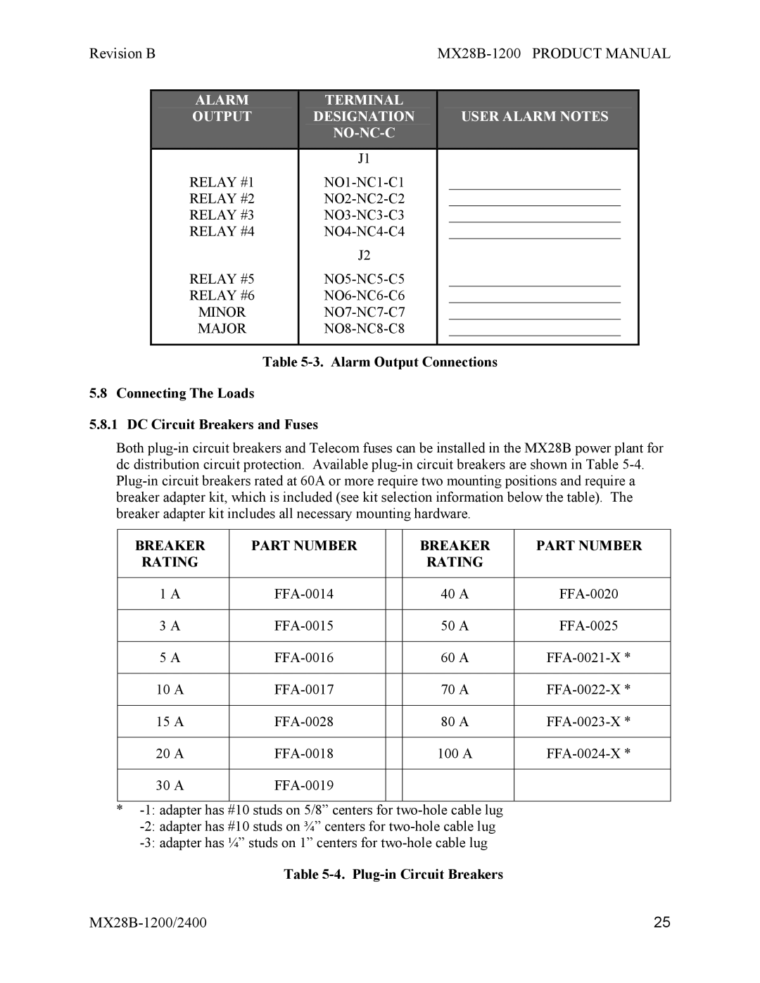
Table 5-3. Alarm Output Connections
5.8 Connecting The Loads
5.8.1 DC Circuit Breakers and Fuses
Both plug-in circuit breakers and Telecom fuses can be installed in the MX28B power plant for dc distribution circuit protection. Available plug-in circuit breakers are shown in Table 5-4. Plug-in circuit breakers rated at 60A or more require two mounting positions and require a breaker adapter kit, which is included (see kit selection information below the table). The breaker adapter kit includes all necessary mounting hardware.
BREAKER | PART NUMBER | | BREAKER | PART NUMBER |
RATING | | | RATING | |
| | | | |
1 A | FFA-0014 | | 40 A | FFA-0020 |
| | | | |
3 A | FFA-0015 | | 50 A | FFA-0025 |
| | | | |
5 A | FFA-0016 | | 60 A | FFA-0021-X * |
| | | | |
10 A | FFA-0017 | | 70 A | FFA-0022-X * |
| | | | |
15 A | FFA-0028 | | 80 A | FFA-0023-X * |
| | | | |
20 A | FFA-0018 | | 100 A | FFA-0024-X * |
| | | | |
30 A | FFA-0019 | | | |
| | | | |
*-1: adapter has #10 studs on 5/8” centers for two-hole cable lug
-2: adapter has #10 studs on ¾” centers for two-hole cable lug
-3: adapter has ¼” studs on 1” centers for two-hole cable lug
Table 5-4. Plug-in Circuit Breakers
