Revision B | PRODUCT MANUAL |
| ||
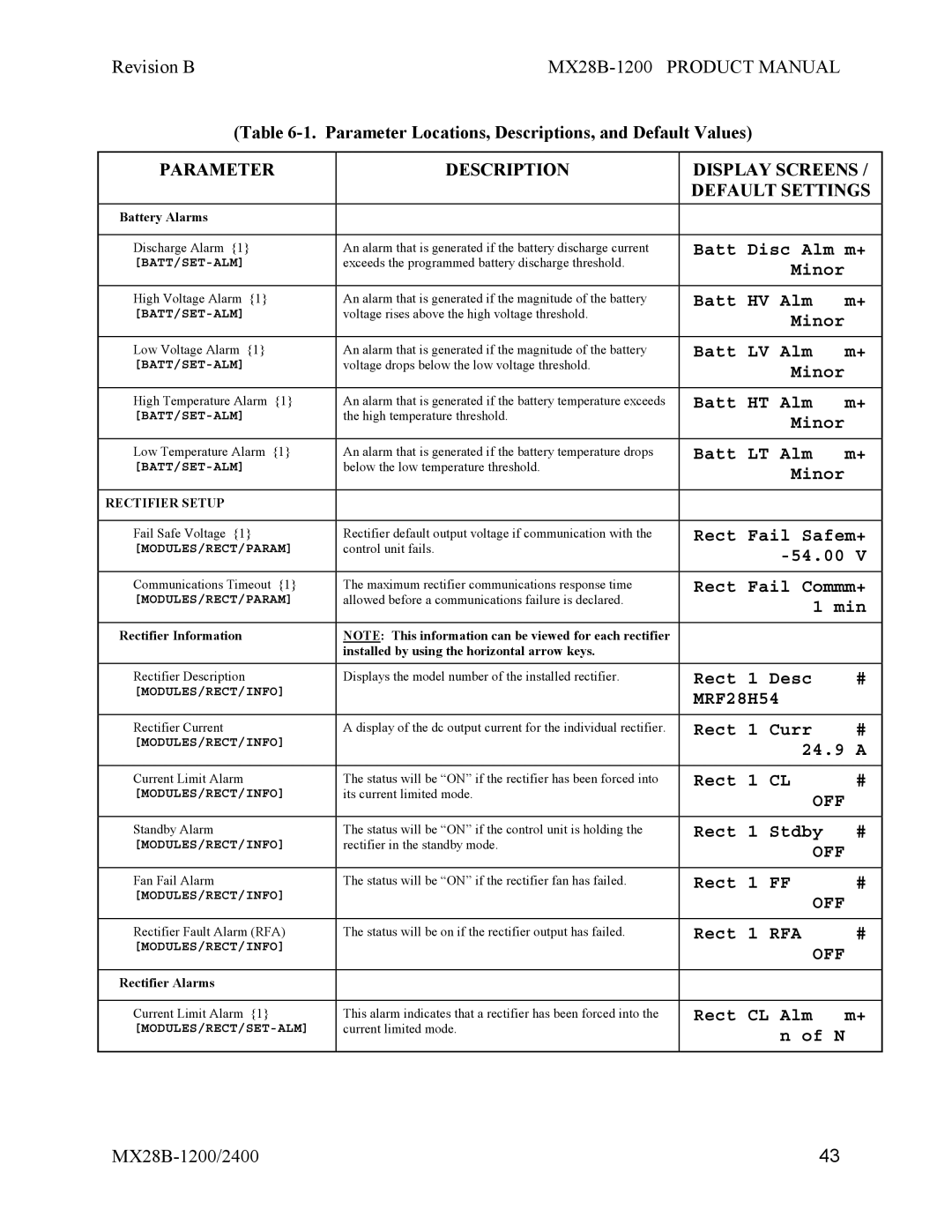
(Table |
| |||
|
|
|
| |
PARAMETER | DESCRIPTION |
| DISPLAY SCREENS / | |
|
|
| DEFAULT SETTINGS | |
Battery Alarms |
|
|
|
|
|
|
|
| |
Discharge Alarm {1} | An alarm that is generated if the battery discharge current |
| Batt Disc Alm m+ | |
exceeds the programmed battery discharge threshold. |
| Minor |
| |
|
|
|
| |
|
|
|
|
|
High Voltage Alarm {1} | An alarm that is generated if the magnitude of the battery |
| Batt HV Alm | m+ |
voltage rises above the high voltage threshold. |
| Minor |
| |
|
|
|
| |
|
|
|
|
|
Low Voltage Alarm {1} | An alarm that is generated if the magnitude of the battery |
| Batt LV Alm | m+ |
voltage drops below the low voltage threshold. |
| Minor |
| |
|
|
|
| |
|
|
|
|
|
High Temperature Alarm {1} | An alarm that is generated if the battery temperature exceeds |
| Batt HT Alm | m+ |
the high temperature threshold. |
| Minor |
| |
|
|
|
| |
|
|
|
|
|
Low Temperature Alarm {1} | An alarm that is generated if the battery temperature drops |
| Batt LT Alm | m+ |
below the low temperature threshold. |
| Minor |
| |
|
|
|
| |
|
|
|
|
|
RECTIFIER SETUP |
|
|
|
|
|
|
|
| |
Fail Safe Voltage {1} | Rectifier default output voltage if communication with the |
| Rect Fail Safem+ | |
[MODULES/RECT/PARAM] | control unit fails. |
| ||
|
|
| ||
|
|
|
| |
Communications Timeout {1} | The maximum rectifier communications response time |
| Rect Fail Commm+ | |
[MODULES/RECT/PARAM] | allowed before a communications failure is declared. |
| 1 min | |
|
|
| ||
|
|
|
| |
Rectifier Information | NOTE: This information can be viewed for each rectifier |
|
| |
| installed by using the horizontal arrow keys. |
|
|
|
|
|
|
|
|
Rectifier Description | Displays the model number of the installed rectifier. |
| Rect 1 Desc | # |
[MODULES/RECT/INFO] |
|
| MRF28H54 |
|
|
|
|
| |
|
|
|
|
|
Rectifier Current | A display of the dc output current for the individual rectifier. |
| Rect 1 Curr | # |
[MODULES/RECT/INFO] |
|
| 24.9 A | |
|
|
| ||
|
|
|
|
|
Current Limit Alarm | The status will be “ON” if the rectifier has been forced into |
| Rect 1 CL | # |
[MODULES/RECT/INFO] | its current limited mode. |
| OFF |
|
|
|
|
| |
|
|
|
|
|
Standby Alarm | The status will be “ON” if the control unit is holding the |
| Rect 1 Stdby | # |
[MODULES/RECT/INFO] | rectifier in the standby mode. |
| OFF |
|
|
|
|
| |
|
|
|
|
|
Fan Fail Alarm | The status will be “ON” if the rectifier fan has failed. |
| Rect 1 FF | # |
[MODULES/RECT/INFO] |
|
| OFF |
|
|
|
|
| |
|
|
|
|
|
Rectifier Fault Alarm (RFA) | The status will be on if the rectifier output has failed. |
| Rect 1 RFA | # |
[MODULES/RECT/INFO] |
|
| OFF |
|
|
|
|
| |
|
|
|
|
|
Rectifier Alarms |
|
|
|
|
|
|
|
|
|
Current Limit Alarm {1} | This alarm indicates that a rectifier has been forced into the |
| Rect CL Alm | m+ |
current limited mode. |
| n of N |
| |
|
|
|
| |
|
|
|
|
|
43 |