| Revision B |
| |
(Table |
| ||
|
|
| |
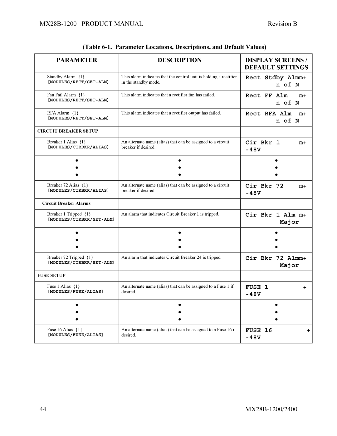
PARAMETER | DESCRIPTION | DISPLAY SCREENS / | |
|
| DEFAULT SETTINGS | |
Standby Alarm {1} | This alarm indicates that the control unit is holding a rectifier | Rect Stdby Almm+ | |
in the standby mode. | n of N |
| |
|
|
| |
|
|
|
|
Fan Fail Alarm {1} | This alarm indicates that a rectifier fan has failed. | Rect FF Alm | m+ |
| n of N |
| |
|
|
| |
|
|
|
|
RFA Alarm {1} | This alarm indicates that a rectifier output has failed. | Rect RFA Alm | m+ |
| n of N |
| |
|
|
| |
|
|
|
|
CIRCUIT BREAKER SETUP |
|
|
|
|
|
|
|
Breaker 1 Alias {1} | An alternate name (alias) that can be assigned to a circuit | Cir Bkr 1 | m+ |
[MODULES/CIRBKR/ALIAS] | breaker if desired. |
|
|
|
|
| |
|
|
|
|
• | • | • |
|
• | • | • |
|
• | • | • |
|
|
|
|
|
Breaker 72 Alias {1} | An alternate name (alias) that can be assigned to a circuit | Cir Bkr 72 | m+ |
[MODULES/CIRBKR/ALIAS] | breaker if desired. |
| |
|
|
| |
|
|
|
|
Circuit Breaker Alarms |
|
|
|
|
|
| |
Breaker 1 Tripped {1} | An alarm that indicates Circuit Breaker 1 is tripped. | Cir Bkr 1 Alm m+ | |
| Major |
| |
|
|
| |
|
|
|
|
• | • | • |
|
• | • | • |
|
• | • | • |
|
|
|
| |
Breaker 72 Tripped {1} | An alarm that indicates Circuit Breaker 24 is tripped. | Cir Bkr 72 Almm+ | |
| Major |
| |
|
|
| |
|
|
|
|
FUSE SETUP |
|
|
|
|
|
|
|
Fuse 1 Alias {1} | An alternate name (alias) that can be assigned to a Fuse 1 if | FUSE 1 | + |
[MODULES/FUSE/ALIAS] | desired. |
| |
|
|
| |
|
|
|
|
• | • | • |
|
• | • | • |
|
• | • | • |
|
|
|
|
|
Fuse 16 Alias {1} | An alternate name (alias) that can be assigned to a Fuse 16 if | FUSE 16 | + |
[MODULES/FUSE/ALIAS] | desired. |
| |
|
|
| |
|
|
|
|
44 |
