The Front Panel
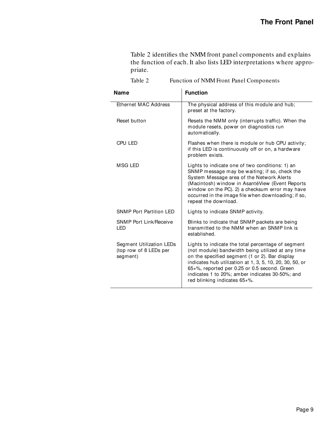
Table 2 identifies the NMM front panel components and explains the function of each. It also lists LED interpretations where appro- priate.
Table 2 Function of NMM Front Panel Components
Name | Function |
|
|
Ethernet MAC Address | The physical address of this module and hub; |
| preset at the factory. |
Reset button | Resets the NMM only (interrupts traffic). When the |
| module resets, power on diagnostics run |
| automatically. |
CPU LED | Flashes when there is module or hub CPU activity; |
| if this LED is continuously off or on, a hardware |
| problem exists. |
MSG LED | Lights to indicate one of two conditions: 1) an |
| SNMP message may be waiting; if so, check the |
| System Message area of the Network Alerts |
| (Macintosh) window in AsantéView (Event Reports |
| window on the PC). 2) a checksum error may have |
| occurred in the image file when downloading; if so, |
| repeat the download. |
SNMP Port Partition LED | Lights to indicate SNMP activity. |
SNMP Port Link/Receive | Blinks to indicate that SNMP packets are being |
LED | transmitted to the NMM when an SNMP link is |
| established. |
Segment Utilization LEDs | Lights to indicate the total percentage of segment |
(top row of 8 LEDs per | (not module) bandwidth being utilized at any time |
segment) | on the specified segment (1 or 2). Bar display |
| indicates hub utilization at 1, 3, 5, 10, 20, 30, 50, or |
| 65+%, reported per 0.25 or 0.5 second. Green |
| indicates 1 to 20%; amber indicates |
| red blinking indicates 65+%. |
|
|
Page 9
