AsantéHub 2072 Network Management Module Installation Guide
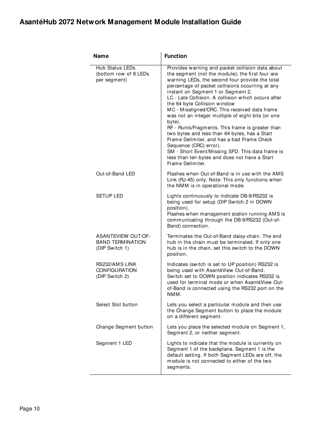
Name | Function |
|
|
Hub Status LEDs | Provides warning and packet collision data about |
(bottom row of 8 LEDs | the segment (not the module); the first four are |
per segment) | warning LEDs, the second four provide the total |
| percentage of packet collisions occurring at any |
| instant on Segment 1 or Segment 2. |
| LC - Late Collision. A collision which occurs after |
| the 64 byte Collision window |
| MC - Misaligned/CRC. This received data frame |
| was not an integer multiple of eight bits (or one |
| byte). |
| RF - Runts/Fragments. This frame is greater than |
| two bytes and less than 64 bytes, has a Start |
| Frame Delimiter, and has a bad Frame Check |
| Sequence (CRC) error). |
| SM - Short Event/Missing SFD. This data frame is |
| less than ten bytes and does not have a Start |
| Frame Delimiter. |
Flashes when | |
| Link |
| the NMM is in operational mode. |
SETUP LED | Lights continuously to indicate |
| being used for setup (DIP Switch 2 in DOWN |
| position). |
| Flashes when management station running AMS is |
| communicating through the |
| Band) connection. |
ASANTEVIEW | Terminates the |
BAND TERMINATION | hub in the chain must be terminated. If only one |
(DIP Switch 1) | hub is in the chain, set this switch to the DOWN |
| position. |
RS232/AMS LINK | Indicates (switch is set to UP position) RS232 is |
CONFIGURATION | being used with AsantéView |
(DIP Switch 2) | Switch set to DOWN position indicates RS232 is |
| used for terminal mode or when AsantéView Out- |
| |
| NMM. |
Select Slot button | Lets you select a particular module and then use |
| the Change Segment button to place the module |
| on a different segment. |
Change Segment button | Lets you place the selected module on Segment 1, |
| Segment 2, or neither segment. |
Segment 1 LED | Lights to indicate that the module is currently on |
| Segment 1 of the backplane. Segment 1 is the |
| default setting. If both Segment LEDs are off, the |
| module is not connected to either of the two |
| segments. |
|
|
Page 10