Installation
Components
This section describes the front- and
The only control on the front panel is the uplink
The uplink
FS7108
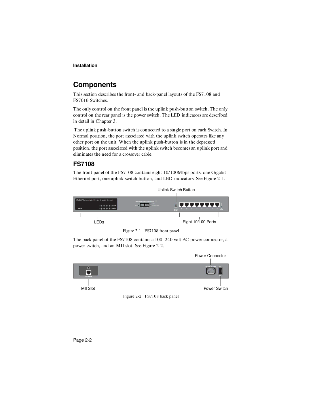
The front panel of the FS7108 contains eight 10/100Mbps ports, one Gigabit Ethernet port, one uplink switch button, and LED indicators. See Figure
|
|
|
|
|
|
|
|
| Uplink Switch Button |
|
|
|
|
|
| ||||
|
|
|
|
|
|
|
|
|
|
|
|
|
|
|
|
|
|
|
|
| FRIENDLYNET 7108 GIGABIT SWITCH | Switched Gigabit Ethernet Port |
|
|
|
|
|
|
|
|
|
|
|
| |||||
|
|
| 100/10Mbps |
|
| Link/Data |
|
|
|
|
|
|
|
|
| ||||
|
|
| Power |
| Full Duplex/Collision |
|
|
|
|
|
|
|
|
|
| ||||
|
|
| Full/Half | TxRx |
|
| Uplink |
|
|
|
|
|
|
|
| MII | |||
Power | Link/Data |
|
|
|
|
|
| 1 | 2 | 3 | 4 | 5 | 6 | 7 | 8 | ||||
1 2 3 4 5 6 | 7 8 |
|
|
|
|
|
| Normal |
|
|
|
|
|
|
|
| Power | ||
|
|
|
|
|
|
|
|
|
| Uplink |
|
|
|
|
|
|
|
|
|
|
|
|
|
|
|
|
|
|
|
|
|
|
|
|
| ||||
|
|
|
|
|
|
|
|
|
|
|
|
|
|
|
|
|
|
|
|
|
|
|
|
|
|
|
|
|
|
|
|
|
|
|
|
|
|
|
|
| LEDs |
|
|
|
|
|
|
|
|
| Eight 10/100 Ports |
|
| ||||||
Figure 2-1 FS7108 front panel
The back panel of the FS7108 contains a
Power Connector
On |
MII Module | Off |
MII Slot | Power Switch |
Figure 2-2 FS7108 back panel
Page
