ACCF/SF Module
Page
Introduction
ATM Terminology
Finding Information in This Guide
Conventions
Page
Contents
Contents
Avaya M770 M-ACCF/SF ATM Access Modules User’s Guide Iii
Contents
Contents
Page
Port Submenu Display Results
List of Figures
Management Submenu
Snmp Submenu
ATM Submenu
List of Tables
Page
ATM Access Modules
Features and Benefits
Overview
ATM Benefits
Avaya M770 Frame Switch Domains
ATM Access Module Features
Wire Rate Transmission on ATM port
LAN Emulation Lane version
Network Layer Concepts LAN Emulation
LAN Emulation Overview
Emulated LAN Components
LAN Emulation Client LEC
LAN Emulation Server LES
LAN Emulation Configuration Server Lecs
Broadcast and Unknown Server BUS
Emulated LAN Connections
Control VCCs
Data VCCs
Frame Ordering
Flush Protocol
Connecting a LEC to an Elan
Operation of the LAN Emulation
Connection Processes of the LEC to Lane Server
Registration
Connection Management
Address Resolution
LAN Emulation Components in Your Network
LAN Emulation and Avaya Devices
An Example
Joining the Elan
LEC must know the name of the Elan it is to join
Locating the Lecs
Mapping Ethernet and ATM Addresses
Address Resolution
If the destination MAC address is listed in the ARP Table
What Happens to Unicast Frames?
LAN Emulation Address Resolution Protocol Learp
What Happens to Broadcast and Multicast Frames?
Network Layer Concepts ATM & ATM Adaptation
Layered Network Architecture
ATM Adaptation Layer AAL
Asynchronous Transfer Mode ATM Layer
ATM Basics
ATM is Service Transparent
Service Processing
ATM is Connection-Oriented
10 Communication Channels
11 Connection Terminology
Virtual Path Identifier VPI Virtual Channel Identifier VCI
12 Switching Cells Using VPI and VCI Values
Switched Virtual Circuits SVCs
ATM Interfaces
Interim Local Management Interface Ilmi
Networkhostidentifier
ATM Address Registration
ATM Layer and Cell Structure
15 ATM Cell Structure
Physical Layer
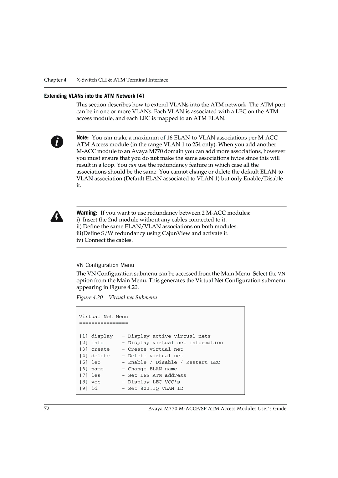
Extending VLANs into the ATM Network
16 Vlan to Elan Mapping
17 Extending VLANs into the ATM Network
Putting Your ATM Network Together
Applications
Planning Your Network
ATM Configuration Rules
Does your network conform to the ATM configuration rules?
What logical network domains, VLANs, do you wish to set up?
Are the LAN Emulation services configured correctly?
Extending VLANs Through the ATM Network
Will you have sufficient Elan resources?
ATM Connections Within Your Network
Network Configuration Examples
ATM Backbone in the Building
ATM Backbone in the Building
Avaya M770 Multitechnology Functionality
Avaya M770 Multitechnology Functionality
Routing in the X-Switch Domain
Routing in the X-Switch Domain
Installing the M-ACC Module
Installation
Safety Information
Pre-installation Procedure
Single-mode Module Laser Classification
Multi-Mode Module LED Warning
Agency Approval
Avaya M770 Module DRU Budget
Domain Usage Considerations
Budget Calculation Examples
DRU Budget Information Window
DRU Budget Information Window
Installing the Module
Connecting a Cable to the ATM Port
Inserting the Module into the Hub
CAM Contents Addressable Memory tests
Power On Self Test
Removing an Existing ATM Access Module
Post-Installation Checks
M-ACC LEDs Descriptions
Configuring the M-ACC Module
ACC Module Default Settings
M-ACC Module Default Settings
Connecting to the Serial Port
Establishing a Telnet Session
For example telnet
Setting up the M-ACC Module
To connect to the M-SPX/S Console port
ATM IP Configuration
Module Setup Main Menu
Assigning the M-ACC module IP address, Gateway and Netmask
There is no need to perform a reset. Configuration Example
Setting up the ATM Access Module
Accmmls Switch
MLS Bridging
Switch CLI & ATM Terminal Interface
Switch Command Line Interface CLI
ACC ATM Access Module Terminal Menu Interface
Introduction
Conventions Used
Switch Command Line Interface CLI
Commands Summary Table
Reset the Module
Software Download to the X-Switch CPU
Entering Software Download Parameters
Starting the Software Download Process
Monitoring the Software Download Process
Set Primary Version
Set Defaults to Factory Settings
Create Report
Configuration Copy
Clear Mac Address Table
Assigning the M-ACC module IP address, Gateway and Netmask
Commands Tree Chart
Logging On
Logging Off
Managing the ATM Access Module
Submenus
Menu Structure of the ATM Access Module
Main Menu Options
Configuring System Parameters
System Menu
Passwords Submenu 1,3
Reset Submenu1,4
Display Submenu 1,1
Initialize Submenu 1,2
Display Flash Log Messages Submenu 1,5,1
System Logger Submenu 1,5
Operational Meanings of Display Flash Log Submenu Items
Display Memory Log Messages Submenu 1,5,2
Operational Meanings of Display Memory Submenu Items
ATM access module Configuration
Configuring an ATM Port
System Software Download Submenu 1,6
Port Submenu 2,1
Operational Meanings of Port Submenu Items
ATM Port Physical Submenu 2,1,6
VCC Submenu 2,2
VCC Submenu Items and their Operational Meanings
Aging Submenu 2,2,4
Snmp Configuration Submenu 3,2
Administering IP and Snmp Management
IP Submenu 3,1
Configure Submenu Items and their Operational Meanings
18 updSysAtt Submenu 3,2,6
VN Configuration Menu
20 Virtual net Submenu
Vlan
Vlan Elan ID
Elan
LEC ATM
LEC
LES ATM
Setting up an ATM VLAN/ELAN
Upgrading Software
Preliminaries
Downloading
Monitoring the ATM Access Module
ATM Port Statistics
22 ATM Port Statistics Screen
Port Statistics Display Items and their Meanings
VCC Statistics
Statistics Display Items and their Meanings
CajunView M770 Device Manager version
Network Management and Monitoring
Cajun LANEMaster version
CajunView M770 Device Manager
Starting the M770 Manager
Running M770 Manager from HP-OV for Windows
Running M770 Manager from HP Windows NT
Overview
LANEMaster
Starting Cajun LANEMaster
Cajun LANEMaster Views
Overview
Cajun LANEMaster Window
Page
Specifications
ACC ATM Access Module Technical Specifications
Environmental, Safety, and EMC Specifications
ATM Cable Specification
Table A.3 Standard Multi-mode Cable Specifications
Optical Standard Supported
ATM Forum
SDH Standard Supported
Table A.4 Standard Multi-mode Cable Specifications
EIA-492CAAA
Safety Information
Important Safety Information
Table B.1 Troubleshooting Tips
Troubleshooting
ELAN/VLAN
Page
Index
Numerics
ATM WAN
SAR
Text
Learp
Luni
LES
ATM VLAN/ELAN
VCC
United States
How to Contact Us
Emea Europe, Middle East and Africa Region
UAE
AP Asia Pacific Region
Avaya.com