8 | Physical Description | AXIS 2100 User’s Guide |
|
|
|
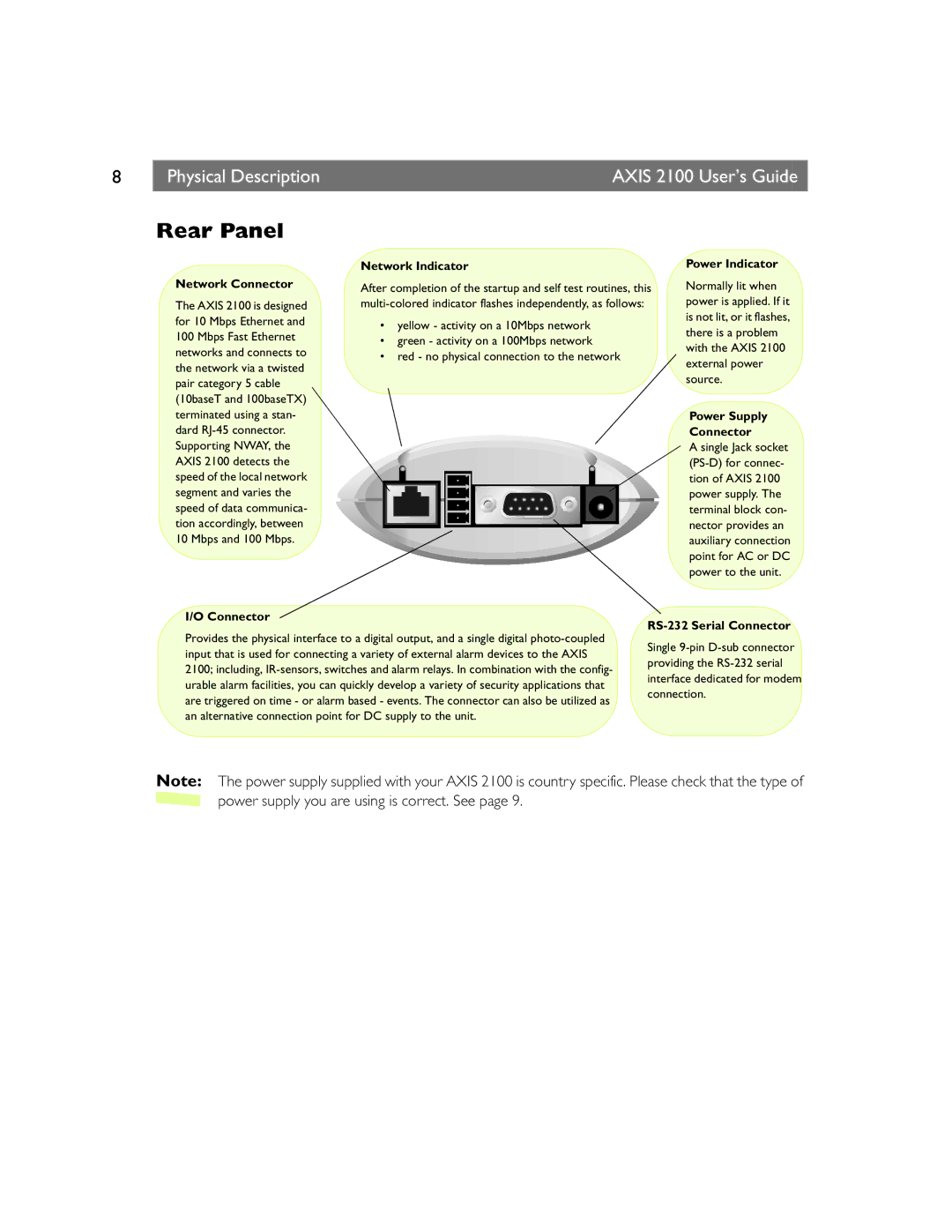
Rear Panel
Network Connector
The AXIS 2100 is designed for 10 Mbps Ethernet and 100 Mbps Fast Ethernet networks and connects to the network via a twisted pair category 5 cable (10baseT and 100baseTX) terminated using a stan- dard
I/O Connector
Network Indicator
After completion of the startup and self test routines, this
•yellow - activity on a 10Mbps network
•green - activity on a 100Mbps network
•red - no physical connection to the network
Power Indicator
Normally lit when power is applied. If it is not lit, or it flashes, there is a problem with the AXIS 2100 external power source.
Power Supply
Connector
A single Jack socket
RS-232 Serial Connector
Provides the physical interface to a digital output, and a single digital
Single
Note: The power supply supplied with your AXIS 2100 is country specific. Please check that the type of ![]() power supply you are using is correct. See page 9.
power supply you are using is correct. See page 9.