AXIS 212 PTZ - Product Features
I/O terminal connector - Pinout
Pin | Function | Description |
|
|
|
4 | Transistor Out- | With a maximum load of 50mA and a maximum voltage of 24V DC, this output has an |
| put | emitter connected to the GND pin. If used with an external relay, a diode must be connected in parallel with the load, for pro- |
|
| tection against voltage transients. |
|
|
|
3 | Digital Input | Connect to GND to activate, or leave floating (or unconnected) to deactivate. |
|
|
|
2 | 3.3V DC | Can be used to power auxiliary equipment, max 50mA. |
|
|
|
1 | GND |
|
|
|
|
LED indicators |
| |
LED | Color | Description |
|
|
|
Network | Green | Steady for connection to 100 Mbit/s network. Flashes for network activity. |
|
|
|
| Amber | Steady for connection to 10 Mbit/s network. Flashes for network activity. |
|
|
|
| Unlit | No connection. |
|
|
|
Status | Green | Shows steady green for normal operation. |
|
| Note: The Status LED can be configured to be unlit during normal operation, or to flash only when the camera is accessed. See the |
|
| online help files for more information. Go to Setup > System Options > LED settings |
|
|
|
| Amber | Steady during startup, reset to factory default or when restoring settings. |
|
|
|
| Red | Slow flash for failed upgrade. |
|
|
|
Power | Green | Normal operation. |
|
|
|
| Amber | Flashes green/amber during firmware upgrade. |
|
|
|
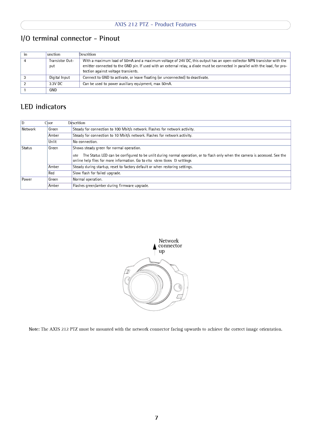
Network connector ![]() up
up
Note: The AXIS 212 PTZ must be mounted with the network connector facing upwards to achieve the correct image orientation.
7