AXIS 230 | Product Description | 9 |
Product Description
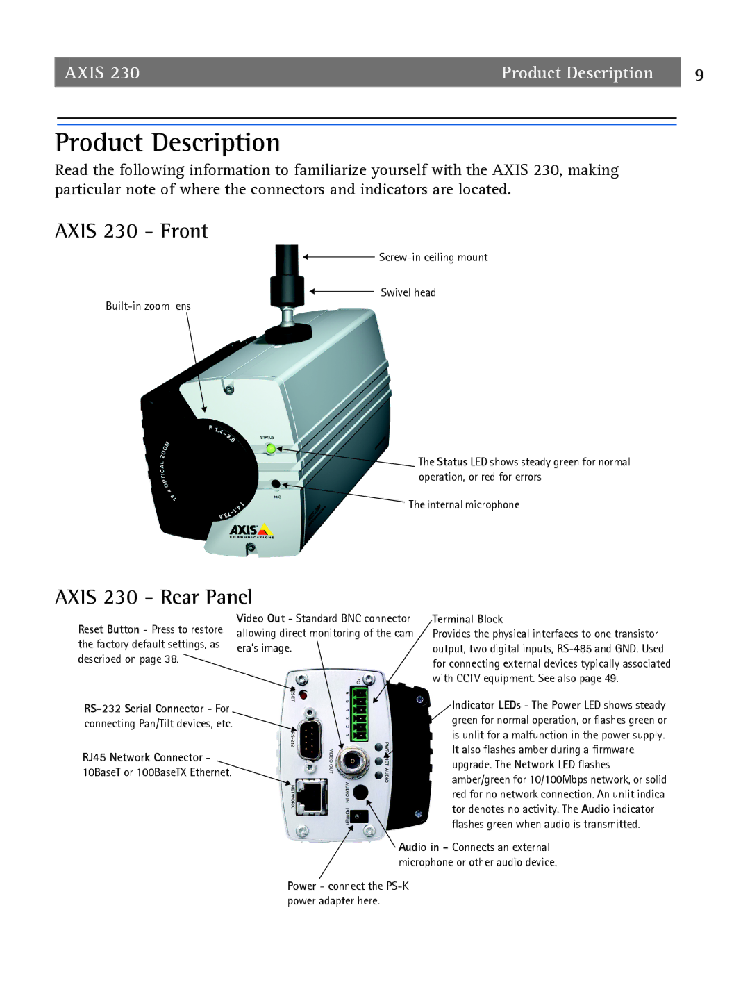
Read the following information to familiarize yourself with the AXIS 230, making particular note of where the connectors and indicators are located.
AXIS 230 - Front
![]()
Swivel head
![]() The Status LED shows steady green for normal operation, or red for errors
The Status LED shows steady green for normal operation, or red for errors
The internal microphone
AXIS 230 - Rear Panel
Reset Button - Press to restore the factory default settings, as described on page 38.
Video Out - Standard BNC connector allowing direct monitoring of the cam- era’s image.
Terminal Block
Provides the physical interfaces to one transistor output, two digital inputs,
| Indicator LEDs - The Power LED shows steady | |
green for normal operation, or flashes green or | ||
connecting Pan/Tilt devices, etc. | ||
is unlit for a malfunction in the power supply. | ||
| ||
RJ45 Network Connector - | It also flashes amber during a firmware | |
upgrade. The Network LED flashes | ||
10BaseT or 100BaseTX Ethernet. | ||
amber/green for 10/100Mbps network, or solid | ||
| ||
| red for no network connection. An unlit indica- | |
| tor denotes no activity. The Audio indicator | |
| flashes green when audio is transmitted. |
Audio in - Connects an external microphone or other audio device.
Power - connect the