Fyrite® INSIGHT

Procedure:

NOTE: The unit-of-measure for pressure is selected per Section 3.5.3. In the following procedure inwc is selected, but note that any unit- of-measure can be used for calibration purposes.

1


2

3

4


4

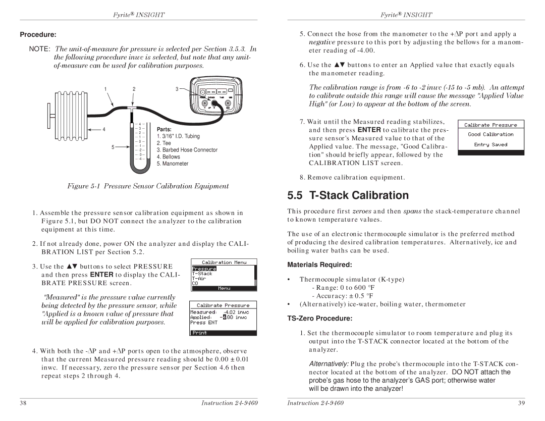
Parts:


3


2

1. 3/16" I.D. Tubing


1


0

2. Tee


5

-1


3. Barbed Hose Connector


-2


-3

4. Bellows


-4

5. Manometer

Figure 5-1 Pressure Sensor Calibration Equipment

1.Assemble the pressure sensor calibration equipment as shown in Figure 5.1, but DO NOT connect the analyzer to the calibration equipment at this time.

2.If not already done, power ON the analyzer and display the CALI- BRATION LIST per Section 5.2.

3.Use the ▲▼ buttons to select PRESSURE

and then press ENTER to display the CALI- BRATE PRESSURE screen.

"Measured" is the pressure value currently being detected by the pressure sensor, while

"Applied is a known value of pressure that-4.02will be applied for calibration purposes.

4.With both the -ΔP and +ΔP ports open to the atmosphere, observe that the current Measured pressure reading should be 0.00 ± 0.01 inwc. If necessary, zero the pressure sensor per Section 4.6 then repeat steps 2 through 4.

Fyrite® INSIGHT

5.Connect the hose from the manometer to the +ΔP port and apply a negative pressure to this port by adjusting the bellows for a manom- eter reading of -4.00.

6.Use the ▲▼ buttons to enter an Applied value that exactly equals the manometer reading.

The calibration range is from -6 to -2 inwc (-15 to -5 mb). An attempt to calibrate outside this range will cause the message "Applied Value High" (or Low) to appear at the bottom of the screen.

7.Wait until the Measured reading stabilizes, and then press ENTER to calibrate the pres- sure sensor's Measured value to that of the Applied value. The message, "Good Calibra- tion" should briefly appear, followed by the CALIBRATION LIST screen.

8.Remove calibration equipment.

5.5 T-Stack Calibration

This procedure first zeroes and then spans the stack-temperature channel to known temperature values.

The use of an electronic thermocouple simulator is the preferred method of producing the desired calibration temperatures. Alternatively, ice and boiling water baths can be used.

Materials Required:

Thermocouple simulator (K-type)

-Range: 0 to 600 °F

-Accuracy: ± 0.5 °F

(Alternatively) ice-water, boiling water, thermometer

TS-Zero Procedure:

1.Set the thermocouple simulator to room temperature and plug its output into the T-STACK connector located at the bottom of the analyzer.

Alternatively: Plug the probe's thermocouple into the T-STACK con- nector located at the bottom of the analyzer. DO NOT attach the probe's gas hose to the analyzer's GAS port; otherwise water will be drawn into the analyzer!

38

Instruction 24-9460


Instruction 24-9460

39

Page 22
Image 22
Bacharach INSIGHT manual Stack Calibration, TS-Zero Procedure

INSIGHT specifications

Bacharach INSIGHT is a cutting-edge platform designed for HVAC professionals and building management teams, providing real-time insights and analytics for optimal system performance. Offering a seamless integration of hardware and software, INSIGHT enhances operational efficiency by transforming traditional data management paradigms.

One of the standout features of Bacharach INSIGHT is its user-friendly interface, which enables users to visualize data in an easily digestible format. The platform presents key metrics, historical trends, and system alerts, empowering users to make informed decisions quickly. This accessibility is crucial for technicians and managers who need to identify potential issues before they escalate, ensuring systems run smoothly and effectively.

Another significant characteristic of Bacharach INSIGHT is its advanced data analytics capabilities. The platform leverages machine learning algorithms to analyze performance data, identify patterns, and predict maintenance needs. This proactive approach minimizes downtime and extends the lifespan of HVAC systems, resulting in cost savings for organizations.

INSIGHT also incorporates IoT technologies, allowing for real-time data collection from various connected devices across an HVAC system. This integration ensures that users have access to accurate and timely information, facilitating immediate responses to any irregularities. The use of cloud technology enables data storage and access from anywhere, promoting collaboration among team members and stakeholders.

The platform is designed with scalability in mind, accommodating small businesses with singular HVAC units as well as large enterprises with complex, multi-site systems. This flexibility means that as organizations grow, Bacharach INSIGHT can adapt to their changing needs without requiring extensive modifications.

Furthermore, user customization options allow for tailored dashboards and alerts, ensuring that each team can focus on the most relevant metrics for their operations. This adaptability contributes to improved user experience, enhancing system usability and engagement.

In summary, Bacharach INSIGHT combines intuitive design, powerful analytics, IoT integration, and scalability to redefine HVAC management. By equipping users with actionable insights and fostering proactive maintenance practices, INSIGHT positions organizations to optimize their energy use, reduce costs, and improve overall system reliability. This innovative platform is pioneering a new era for HVAC professionals, facilitating smarter building management with robust, real-time analytics.