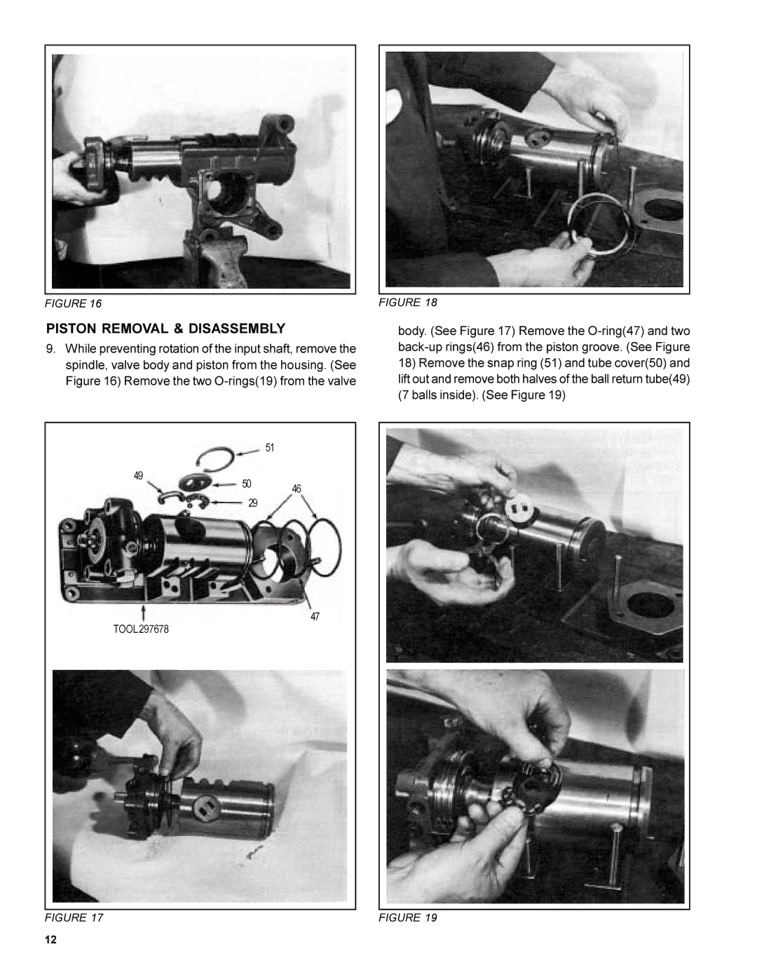
FIGURE 16
PISTON REMOVAL & DISASSEMBLY
9.While preventing rotation of the input shaft, remove the spindle, valve body and piston from the housing. (See Figure 16) Remove the two
FIGURE 18
body. (See Figure 17) Remove the
18)Remove the snap ring (51) and tube cover(50) and lift out and remove both halves of the ball return tube(49) (7 balls inside). (See Figure 19)
49
51
50 46
29
47
TOOL 297678
FIGURE 17 | FIGURE 19 |
12