4.Separate the valve body from the housing by rotating the output shaft using the pitman arm if it has not been previously removed. Continue to separate the valve body from the housing until one of the
NOTE: It may be necessary to hold or rotate the input shaft to perform this operation. (See Figure 10)
FIGURE 8
FIGURE 9
FIGURE 10
5.Remove the pitman arm by unbending the nut lock (21) and remove the pitman arm fastening nut. Remove the pitman arm using a large gear puller such as the “Snap- On”
CAUTION: Do not use heat or pound on the pitman arm or output shaft as damage can result. These components must be replaced rather than repaired if they are damaged. Remove any accumulated dirt, grease, grime, and corrosion from the exposed portion of the output shaft to facilitate removal through its seal. (See Figure 7)
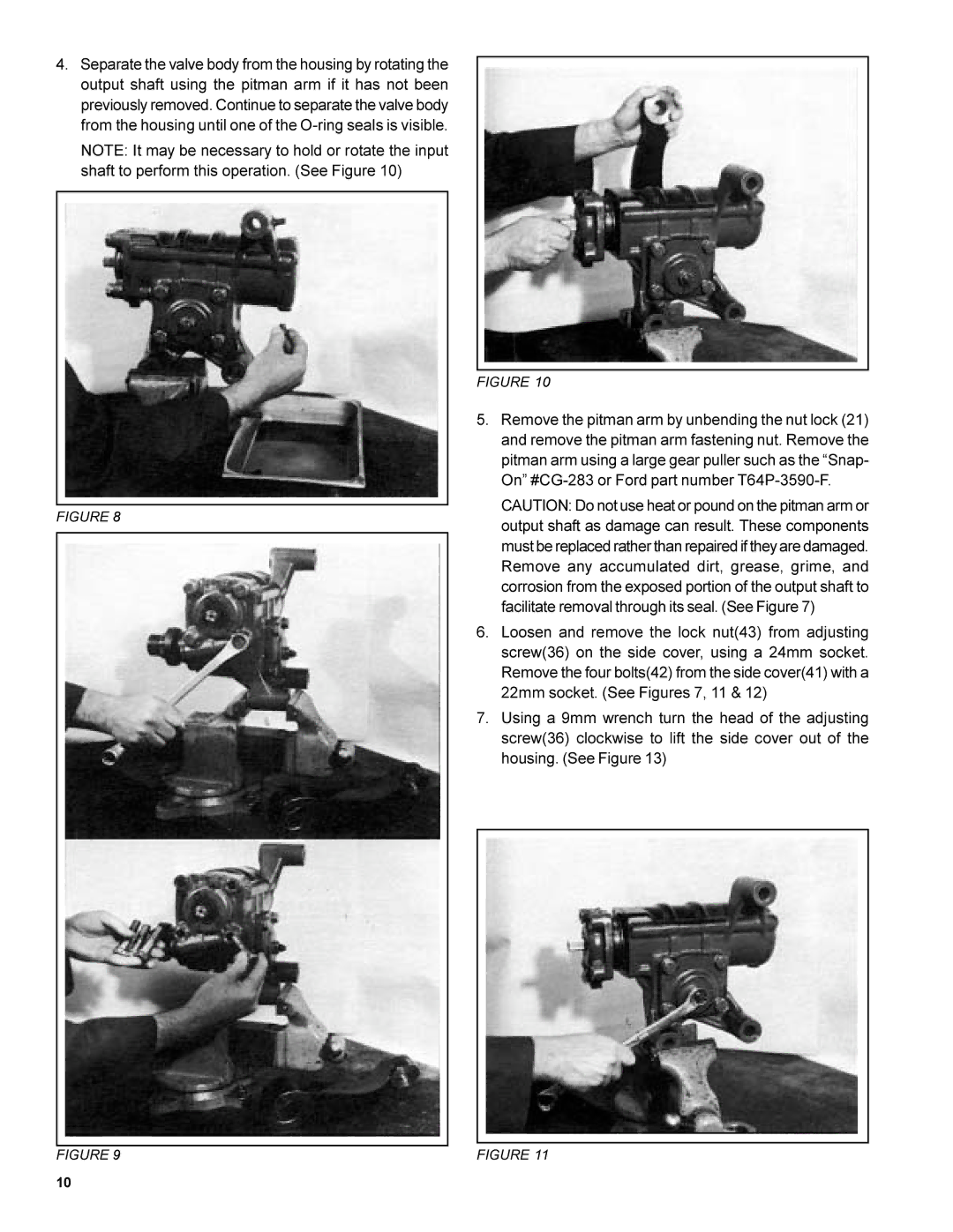
6.Loosen and remove the lock nut(43) from adjusting screw(36) on the side cover, using a 24mm socket. Remove the four bolts(42) from the side cover(41) with a 22mm socket. (See Figures 7, 11 & 12)
7.Using a 9mm wrench turn the head of the adjusting screw(36) clockwise to lift the side cover out of the housing. (See Figure 13)
FIGURE 11
10