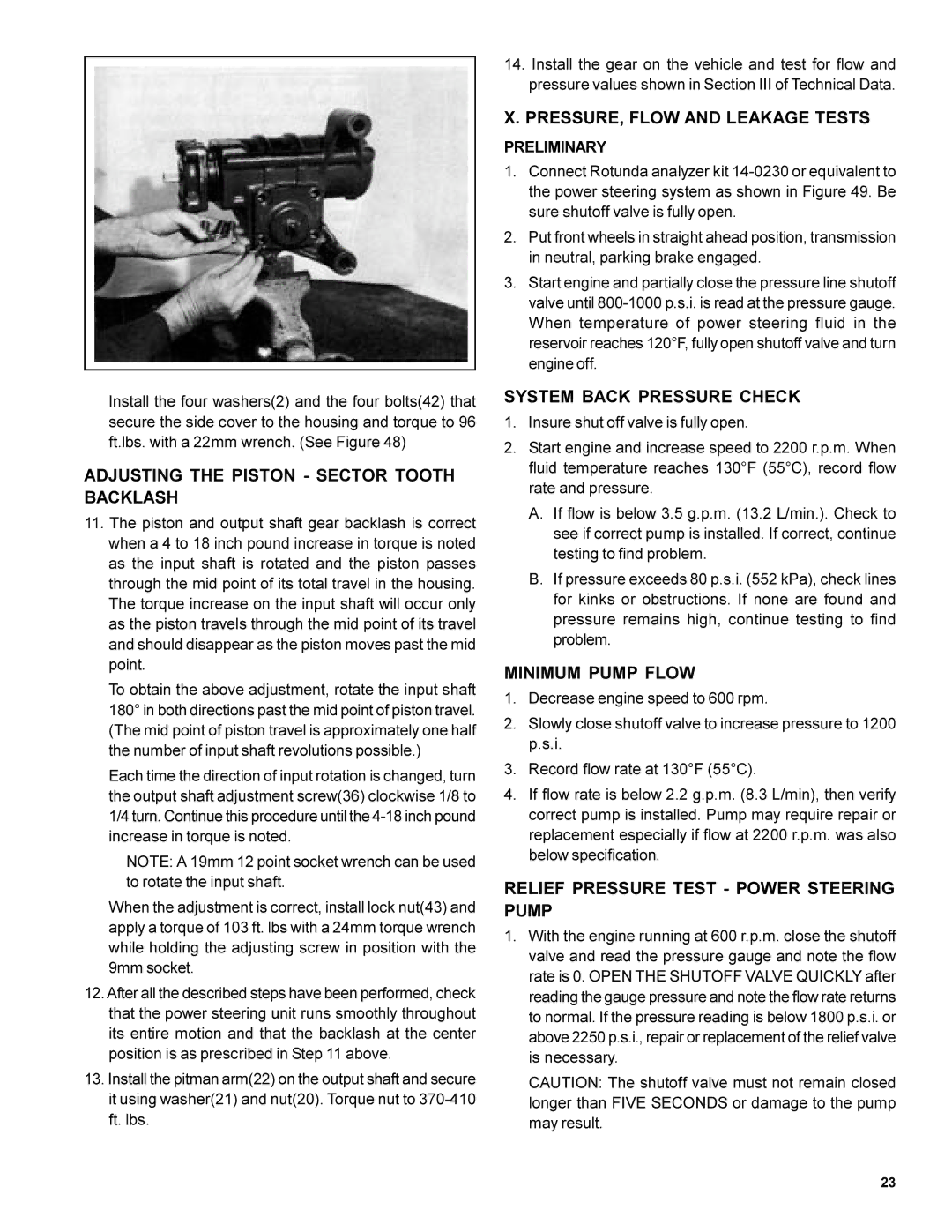
FIGURE 48
Install the four washers(2) and the four bolts(42) that secure the side cover to the housing and torque to 96 ft.lbs. with a 22mm wrench. (See Figure 48)
ADJUSTING THE PISTON - SECTOR TOOTH BACKLASH
11.The piston and output shaft gear backlash is correct when a 4 to 18 inch pound increase in torque is noted as the input shaft is rotated and the piston passes through the mid point of its total travel in the housing. The torque increase on the input shaft will occur only as the piston travels through the mid point of its travel and should disappear as the piston moves past the mid point.
To obtain the above adjustment, rotate the input shaft 180° in both directions past the mid point of piston travel. (The mid point of piston travel is approximately one half the number of input shaft revolutions possible.)
Each time the direction of input rotation is changed, turn the output shaft adjustment screw(36) clockwise 1/8 to 1/4 turn. Continue this procedure until the
NOTE: A 19mm 12 point socket wrench can be used to rotate the input shaft.
When the adjustment is correct, install lock nut(43) and apply a torque of 103 ft. lbs with a 24mm torque wrench while holding the adjusting screw in position with the 9mm socket.
12.After all the described steps have been performed, check that the power steering unit runs smoothly throughout its entire motion and that the backlash at the center position is as prescribed in Step 11 above.
13.Install the pitman arm(22) on the output shaft and secure it using washer(21) and nut(20). Torque nut to
14.Install the gear on the vehicle and test for flow and pressure values shown in Section III of Technical Data.
X. PRESSURE, FLOW AND LEAKAGE TESTS
PRELIMINARY
1.Connect Rotunda analyzer kit
2.Put front wheels in straight ahead position, transmission in neutral, parking brake engaged.
3.Start engine and partially close the pressure line shutoff valve until
SYSTEM BACK PRESSURE CHECK
1.Insure shut off valve is fully open.
2.Start engine and increase speed to 2200 r.p.m. When fluid temperature reaches 130°F (55°C), record flow rate and pressure.
A.If flow is below 3.5 g.p.m. (13.2 L/min.). Check to see if correct pump is installed. If correct, continue testing to find problem.
B.If pressure exceeds 80 p.s.i. (552 kPa), check lines for kinks or obstructions. If none are found and pressure remains high, continue testing to find problem.
MINIMUM PUMP FLOW
1.Decrease engine speed to 600 rpm.
2.Slowly close shutoff valve to increase pressure to 1200 p.s.i.
3.Record flow rate at 130°F (55°C).
4.If flow rate is below 2.2 g.p.m. (8.3 L/min), then verify correct pump is installed. Pump may require repair or replacement especially if flow at 2200 r.p.m. was also below specification.
RELIEF PRESSURE TEST - POWER STEERING PUMP
1.With the engine running at 600 r.p.m. close the shutoff valve and read the pressure gauge and note the flow rate is 0. OPEN THE SHUTOFF VALVE QUICKLY after reading the gauge pressure and note the flow rate returns to normal. If the pressure reading is below 1800 p.s.i. or above 2250 p.s.i., repair or replacement of the relief valve is necessary.
CAUTION: The shutoff valve must not remain closed longer than FIVE SECONDS or damage to the pump may result.
23